Impeller for spray processing device, manufacturing method of impeller, and spray processing device

A processing device and impeller technology, applied in the direction of manufacturing tools, additive manufacturing, impellers, etc., can solve the problems of air compression and air flow rate without considering the flow path of abrasive materials

Active Publication Date: 2022-06-21
FUJI MFG CO LTD
View PDF15 Cites 0 Cited by
  • Summary
  • Abstract
  • Description
  • Claims
  • Application Information

AI Technical Summary

Problems solved by technology

[0015] Here, the centrifugal acceleration device of the jet processing device is also, as its name indicates, a device for accelerating the abrasive material by imparting centrifugal force. The problem of centrifugal force imparted by the material was designed, and the design did not consider the compression of the air in the abrasive material flow path 132, 232 and the flow rate of the air.

Method used


Image

  • Impeller for spray processing device, manufacturing method of impeller, and spray processing device
  • Impeller for spray processing device, manufacturing method of impeller, and spray processing device
  • Impeller for spray processing device, manufacturing method of impeller, and spray processing device

Examples


Embodiment Construction

[0086] Next, embodiments of the present invention will be described with reference to the drawings.

[0087] (Overall structure of blasting machine)

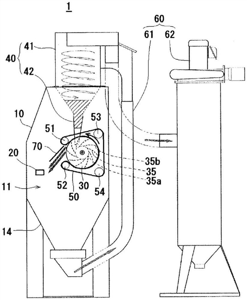
[0088] figure 1 The whole structure of the blast processing apparatus 1 of this invention is shown.

[0089] The blast machining apparatus 1 is configured to project the abrasive material to the workpiece 20 in the machining chamber 11 formed in the housing 10 so as to prevent the scattering of abrasive material and cutting powder, etc., and cause pollution of the working environment. The object 20 is provided on the side wall of the casing 10 in a state capable of opening and closing with respect to an entrance (not shown) for entering and exiting the processing chamber 11 .

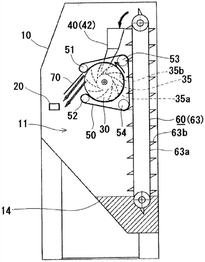
[0090] The machining chamber 11 includes an impeller 30 as an abrasive acceleration mechanism, an abrasive supply mechanism 40 for supplying abrasive to the impeller, and a covering mechanism 50 for covering the outer periphery of the impeller 30 excep...


PUM


Abstract

The present invention provides an impeller for a jet processing device capable of more efficiently accelerating abrasives, a method of manufacturing the impeller, and a jet processing device. The impeller has a disc shape with a predetermined thickness, and has an abrasive material inlet (31), and is formed with a plurality of abrasive material flow paths (32) penetrating within the thickness at predetermined intervals in the circumferential direction, and the abrasive material The flow path (32) has an inlet (32a) communicating with the abrasive material inlet (31) and an outlet (32b) opened on the outer peripheral surface. The abrasive material flow path (32) is arranged with a large inclination relative to the radial direction of the impeller (30) in such a way that the end portion on the outlet (32b) side faces the rear side in the direction of rotation of the impeller (30), thereby greatly reducing the rotational resistance and effectively The acceleration of the abrasive material and the compression of the air in the abrasive material flow path (32) are performed, and the abrasive material is accelerated by centrifugal force and jet flow of compressed air.

Description

technical field [0001] The present invention relates to an impeller for accelerating abrasives of a blast machining device, a blast machining device including the impeller as an abrasive accelerating mechanism, and a method of manufacturing the impeller. Background technique [0002] A blast machining apparatus that projects an abrasive such as abrasive grains toward a workpiece to cut or polish the workpiece includes an abrasive accelerator for projecting the abrasive toward the workpiece. [0003] Examples of such abrasive accelerators include air-type accelerators that accelerate abrasives by jetting them together with compressed air through nozzles, centrifugal-type accelerators that accelerate abrasives by imparting centrifugal force with a rotating impeller, and A launch-type accelerator, etc., in which the pellets are accelerated by hitting a rotating blade. [0004] The impeller 130 provided in the centrifugal acceleration device is a disc with a plurality of blades...

Claims


Application Information

Patent Timeline
Patent Type & Authority Patents(China)
IPC IPC(8): B24C5/06B22F3/105B33Y30/00
CPCB33Y30/00B24C5/06B22F10/00B22F10/20B24C5/062Y02P10/25B33Y80/00
Inventor 间瀬恵二
Owner FUJI MFG CO LTD
Why Eureka
Try Eureka