
A Machine Vision-Based Automobile Tire Pattern Recognition Method

An automobile tire and identification method technology, applied in the field of automobile tire pattern detection, can solve the problems of large human factors, measured data errors, restricting the working efficiency of automobile inspection lines, etc., and achieves high measurement accuracy, good accuracy and robustness. Effect

Active Publication Date: 2020-06-30
SHANDONG JIAOTONG UNIV
View PDF6 Cites 0 Cited by
  • Summary
  • Abstract
  • Description
  • Claims
  • Application Information

AI Technical Summary

Problems solved by technology

[0003] The existing tire wear measurement method generally adopts the method of visual inspection. This method evaluates people's intuitive judgment, and the human factor is very large, so the accuracy cannot be guaranteed.
Another method of measuring tire wear is to measure the tread depth. This method is mainly performed by the inspector using a tire tread depth gauge for contact measurement. Due to the operation method of the inspector and the error of the tire tread depth gauge itself, the measurement will be incorrect. Large errors occur in the data, and the manual measurement efficiency is low, which seriously restricts the work efficiency of the automobile inspection line

Method used


Image

  • A Machine Vision-Based Automobile Tire Pattern Recognition Method
  • A Machine Vision-Based Automobile Tire Pattern Recognition Method
  • A Machine Vision-Based Automobile Tire Pattern Recognition Method

Examples


Embodiment Construction

[0056] Embodiments of the present invention are described in detail below, examples of which are shown in the drawings, wherein the same or similar reference numerals designate the same or similar elements or elements having the same or similar functions throughout. The embodiments described below by referring to the figures are exemplary only for explaining the present invention and should not be construed as limiting the present invention.

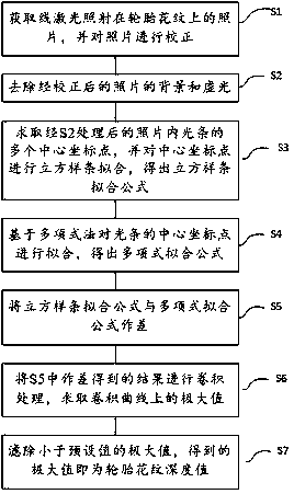
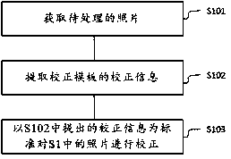
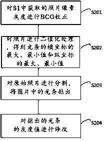
[0057] figure 1 It is a flow chart of the steps of the specific embodiment of the present invention; figure 2 It is a flow chart of the specific steps of S1 in the specific embodiment of the present invention; image 3 It is a flow chart of the specific steps of S2 in the specific embodiment of the present invention; Figure 4 It is a flow chart of the specific steps of S3 in the specific embodiment of the present invention; Figure 5 It is the original light bar diagram of a tire pattern in a specific embodiment of the present inventi...


PUM


Abstract

The invention discloses an automobile tyre pattern recognition method based on machine vision, and the method specifically comprises the following steps: S1, obtaining an image of linear laser on a tyre pattern, and correcting the image; S2, removing the background and vignette of the corrected image; S3, solving a plurality of central coordinate points of a light bar on the processed image at step S2, carrying out the cubic spline fitting of the central coordinate points, and obtaining a cubic spline fitting formula; S4, carrying out the fitting of the central coordinate points of the light bar based on a polynomial method, and obtaining a polynomial fitting formula; S5, solving the difference between the cubic spline fitting formula and the polynomial fitting formula; S6, carrying out the convolution of the difference result at step S5, and solving the maximum values of a convolution curve; S7, filtering the maximum value less than a preset value, wherein the obtained maximum value is the depth value of the tyre pattern. The method can achieve the accurate and efficient recognition of the tyre pattern and the measurement of the depth of the tyre pattern, and is very high in precision and robustness.

Description

technical field [0001] The invention relates to the technical field of automobile tire pattern detection, in particular to a machine vision-based automobile tire pattern recognition method. Background technique [0002] The main function of the pattern of automobile tires is to increase the friction between the tread and the road surface, remove water, and prevent the wheels from slipping. Under the action of braking force and lateral force), the pattern can produce large tangential elastic deformation. As the tangential force increases, the tangential deformation increases, and the "friction effect" of the contact surface is also enhanced, thereby inhibiting the tendency of the tread and the road to slip or slip. This largely eliminates the disadvantages of non-patterned (smooth tread) tires that are easy to slip, making the car performance related to the friction performance between the tire and the road surface - power, braking, steering and driving safety. Normal perfo...

Claims


Application Information

Patent Timeline
Patent Type & Authority Patents(China)
IPC IPC(8): G01B11/22
CPCG01B11/22
Inventor 李爱娟王希波王传胜吴春民慈勤蓬
Owner SHANDONG JIAOTONG UNIV
Learn More