Clean gas cabin

A pure and gas chamber technology, applied in the field of pure gas chamber, can solve the problems of increased bottom load and heavy weight of the inert gas shell, and achieve the effect of small weight, high mechanical load capacity and simplified installation

Active Publication Date: 2017-11-21
布劳恩惰性气体系统有限公司 +1
View PDF10 Cites 4 Cited by
  • Summary
  • Abstract
  • Description
  • Claims
  • Application Information

AI Technical Summary

Problems solved by technology

The disadvantage of such an inert gas housing is its high weight, which is caused by the described construction and the materials used
On the one hand, the large weight makes it difficult to buckle the cover upside down on the corresponding equipment, because there must be a lifting device capable of corresponding loads
Additionally, inert gas enclosures increase bottom loads in addition to the enclosed equipment
This requires extensive and expensive retrofitting measures to improve ground statics in cases where the ground load capacity of buildings requiring pure air chambers is insufficient

Method used


Image

  • Clean gas cabin
  • Clean gas cabin
  • Clean gas cabin

Examples


Embodiment Construction

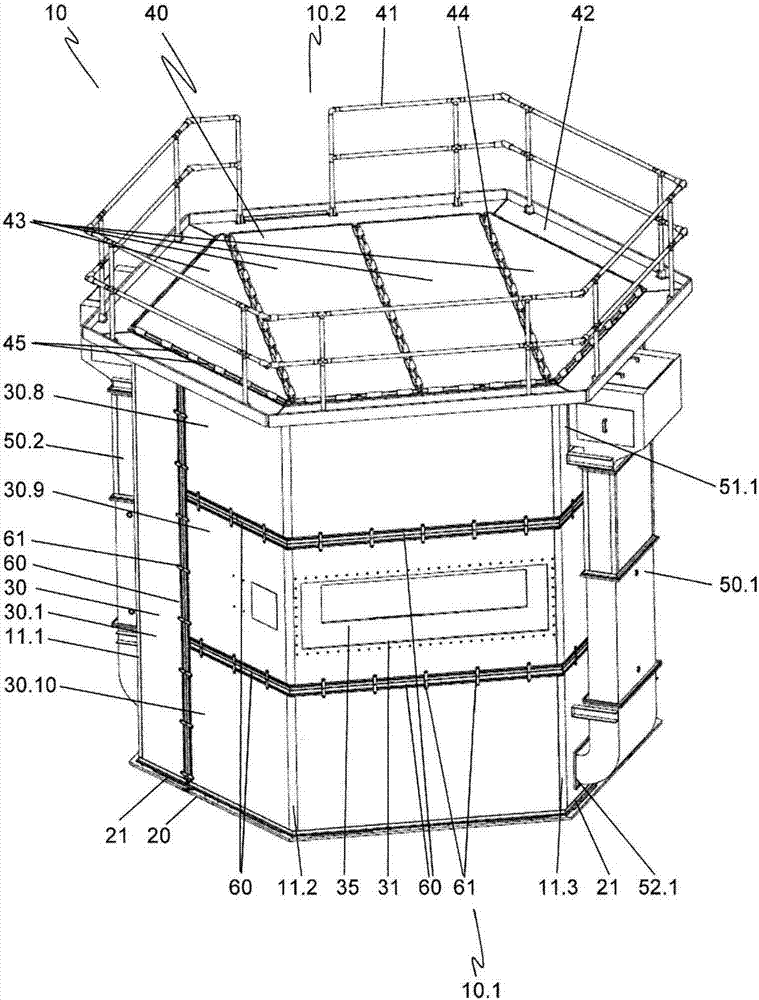
[0046] figure 1 The pure gas chamber 10 is shown in a perspective external view. For easier transfer to the following embodiments, the front side 10.1 and the rear side 10.2 of the pure gas chamber 10 are freely set.

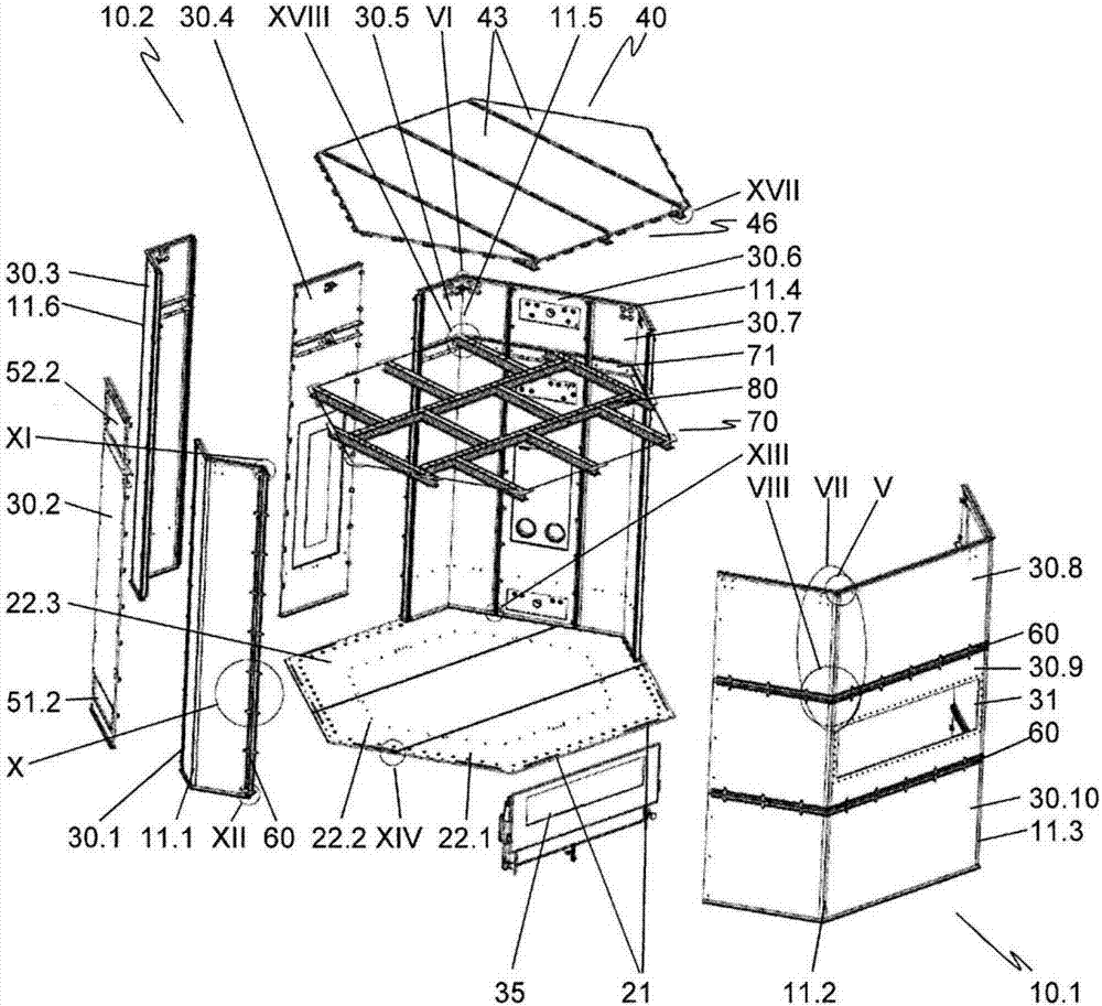
[0047] The pure gas chamber 10 has a polygonal plan shape. In the illustrated embodiment, the planar shape is a hexagon. A plurality of side walls 30 are built on the corresponding hexagonal base 20 . For this purpose, the side walls 30 are oriented according to the positioning element 21 which is mounted on the outer side of the base 20 . In the selected view of the front side 10.1, the left side is provided with a first vertical side wall 30.1 and a first horizontal side wall 30.8, a second horizontal side wall 30.9 and a third horizontal side wall 30.10 arranged one above the other. Other vertical side walls 30.2, 30.3, 30.4, 30.5, 30.6, 30.7 are in image 3 shown in . The first vertical side wall 30.1 comprises the first corner 11.1 of the pure gas cha...


PUM


Abstract

The invention relates to a clean gas cabin (10) having an interior that is sealed off from the environment and surrounded by side walls (30, 30.1-30.10). According to the invention at least some of the side walls of the clean gas cabin are formed of one or more structured-core plates (12), in particular one or more honeycomb-core plates, each having two cover plates (12.1, 12.2) and a structured core (12.3), in particular a honeycomb core, arranged therebetween, and that, along a corner of the clean gas cabin, the one cover plate is bent and the other cover plate and the structured core are separated. The construction of the clean gas cabin using structured-core plates leads to a considerable weight reduction of the clean gas cabin.

Description

technical field [0001] The invention relates to a pure gas chamber which has an inner space enclosed by side walls which is sealed from the surroundings. Background technique [0002] A large number of manufacturing processes and procedures in production and research and development cannot be carried out under ordinary environmental conditions, but require special atmospheres. Such manufacturing processes can be coating processes, e.g. in semiconductor manufacturing; encapsulation steps in LCD or OLED manufacturing or manufacturing processes of high-purity raw materials, e.g. in the medical and pharmaceutical fields; and in welding applications, e.g. titanium welding . These processes may, for example, require clean room conditions, low humidity, an inert gas atmosphere, or various combinations of these and other conditions. [0003] It is known that such manufacturing processes or procedures are carried out in closed spaces in which the atmosphere can be set according to ...

Claims


Application Information

Patent Timeline
Patent Type & Authority Applications(China)
IPC IPC(8): E04B1/12E04B1/343E04H5/02E04H15/62B01L1/04
CPCB01L1/04E04B1/12E04B1/34321E04B2001/0092E04H5/02E04H15/62E04B1/3483E04B1/34869
Inventor G·施普赖策M·克普克T·布尔特曼
Owner 布劳恩惰性气体系统有限公司
Why Eureka
Try Eureka