Trash can type vacuum cleaner
A technology for vacuum cleaners and trash cans, which is applied to the installation of vacuum cleaners, suction nozzles, and electrical equipment. It can solve the problems of poor dust separation and settlement, occupying space, and inconvenient storage, so as to achieve flexible and convenient movement and reduce air flow noise. , the effect of extending the flow distance
Inactive Publication Date: 2017-11-24
JIANGSU MIDEA CLEANING APPLIANCES
10 Cites 0 Cited by
AI-Extracted Technical Summary
Problems solved by technology
However, when the vacuum cleaner is not in use, it is inconvenient to store and takes up space
Moreover, when the vacuum cleaner is cleani...
Abstract
The invention discloses a trash can type vacuum cleaner. The trash can type vacuum cleaner comprises a can body component, a can cover component, a floor brush component, a dust cup component, an air channel component, a driving component and a moving component. The air channel component is divided into an air inlet channel and an air outlet channel. Both the air inlet channel and the air outlet channel are communicated with the dust cup component. The inlet of the air inlet channel is formed in the can body component and located at the lower portion of the can body component. The outlet of the air outlet channel is formed in the can body component and located at the lower portion of the can body component. The driving component is arranged on the can cover component and located in the air outlet channel, and air flow flows towards the outlet of the air outlet channel after avoiding the driving component. According to the trash can type vacuum cleaner, the driving component is arranged on the can cover component and located in the air outlet channel, and thus the air flow after filtration and dust-removing needs to avoid the driving component to flow towards the outlet of the air outlet channel. Therefore, the flowing distance of the air flow in the air channel component is increased, so that outflow rate of air in the outlet of the air outlet channel is reduced, and the air flowing noise is lowered.
Application Domain
Suction nozzlesElectric equipment installation
Technology Topic
AirflowVacuum cleaner +4
Image
Examples
- Experimental program(1)
Example Embodiment
[0123] Embodiments of the invention are described in detail below, examples of which are illustrated in the accompanying drawings. The embodiments described below by referring to the figures are exemplary and are intended to explain the present invention and should not be construed as limiting the present invention.
[0124] In describing the present invention, it should be understood that the terms "center", "longitudinal", "transverse", "length", "width", "thickness", "upper", "lower", "front", " Back", "Left", "Right", "Vertical", "Horizontal", "Top", "Bottom", "Inner", "Outer", "Clockwise", "Counterclockwise", "Axial" , "radial", "circumferential" and other indicated orientations or positional relationships are based on the orientations or positional relationships shown in the drawings, which are only for the convenience of describing the present invention and simplifying the description, rather than indicating or implying the referred device or Elements must have certain orientations, be constructed and operate in certain orientations, and therefore should not be construed as limitations on the invention.
[0125]In addition, the terms "first" and "second" are used for descriptive purposes only, and cannot be interpreted as indicating or implying relative importance or implicitly specifying the quantity of indicated technical features. Thus, the features defined as "first" and "second" may explicitly or implicitly include at least one of these features. In the description of the present invention, "plurality" means at least two, such as two, three, etc., unless otherwise specifically defined.
[0126] In the present invention, unless otherwise clearly specified and limited, terms such as "installation", "connection", "connection" and "fixation" should be understood in a broad sense, for example, it can be a fixed connection or a detachable connection , or integrated; can be mechanically connected, can also be electrically connected or can communicate with each other; can be directly connected, can also be indirectly connected through an intermediary, can be the internal communication of two components or the interaction relationship between two components, Unless expressly defined otherwise. Those of ordinary skill in the art can understand the specific meanings of the above terms in the present invention according to specific situations.
[0127] Refer below Figure 1-Figure 87 A trash can type vacuum cleaner 100 according to an embodiment of the present invention will be described.
[0128] like Figure 1-Figure 15 As shown, the garbage can-type vacuum cleaner 100 according to the embodiment of the present invention includes a bucket body assembly 1 , a bucket lid assembly 2 , a floor brush assembly 4 , a dust cup assembly 5 , an air duct assembly 7 , a driving assembly 93 and a moving assembly 94 .
[0129] Specifically, as Figure 12-Figure 14 As shown, the upper end of the barrel assembly 1 has a barrel opening 142 , and the barrel cover assembly 2 is pivotably connected with the barrel assembly 1 to open or close the barrel opening 142 . The user can open the lid assembly 2 to throw rubbish into the barrel, the barrel assembly 1 can be used as a trash can, and the lid assembly 2 can cover the garbage in the barrel assembly 1, avoiding the exposure of garbage and improving the user's visual appearance sex. When the vacuum cleaner 100 does not need to be used, it can be placed in the living room or study room, which is where the trash can is normally placed in the home, and used as a trash can, which can solve the problem that the vacuum cleaner 100 takes up space when it is not in use .
[0130] like Figure 1-Figure 15 As shown, the ground brush assembly 4 is arranged on the outer bottom wall of the barrel assembly 1. When the vacuum cleaner 100 is moved, the ground brush assembly 4 can be in contact with the ground, and the ground brush assembly 4 can sweep up the dust on the ground so that the vacuum cleaner 100 can absorb it. Dust is beneficial to improve the cleanliness of the ground. The dust cup assembly 5 is located on the bung assembly 2, such as Figure 9 and Figure 11 As shown, the dust cup assembly 5 is provided on the bucket cover assembly 2 , and the dust cup assembly 5 can accommodate the dust absorbed by the vacuum cleaner 100 .
[0131] like Figure 62-Figure 69 As shown, the air duct assembly 7 defines an air inlet air duct 71 and an air outlet air duct 72, the air inlet air duct 71 is arranged on the barrel assembly 1, the air inlet air duct 71 and the air outlet air duct 72 are connected with the dust cup assembly 5 Connected, a part of the air outlet air passage 72 is arranged on the barrel cover assembly 2, another part of the air outlet air passage 72 is arranged on the barrel assembly 1, and the air inlet 711 of the air inlet air passage 71 is arranged on the barrel assembly 1 and located at In the lower part of the barrel assembly 1 , the air outlet 712 of the air outlet duct 72 is located in the barrel assembly 1 and located at the lower part of the barrel assembly 1 . Thus, dust can enter the air duct assembly 7 through the air inlet duct inlet 711 at the bottom of the barrel assembly 1, and the airflow with dust enters into the cup body 51 on the bung cover assembly 2 through the air intake duct 71, and the dust is The inside of the cup body 51 is collected, and the dust-removed wind is discharged from the air outlet duct 72 at the bottom of the barrel assembly 1 .
[0132] like Figure 9 and Figure 11 As shown, the driving member is disposed on the lid assembly 2 and is located in the air outlet duct 72 , and the air flow bypasses the driving assembly 93 and then flows toward the outlet 712 of the air outlet duct. Thus, the flow distance of the airflow in the air duct assembly 7 can be extended, thereby reducing the outflow velocity of the airflow at the outlet 712 of the air outlet duct, thereby reducing the flow noise of the airflow.
[0133] like figure 2 , Figure 4 and Figure 5 As shown, the moving assembly 94 is disposed at the bottom of the barrel assembly 1 and spaced apart from the ground brush assembly 4 . When the vacuum cleaner 100 needs to be moved, the moving assembly 94 rotates so that the vacuum cleaner 100 can move freely, so as to realize vacuuming in different places.
[0134] According to the garbage can-type vacuum cleaner 100 of the embodiment of the present invention, by setting the driving assembly 93 on the lid assembly 2 and in the air outlet duct 72, the filtered and dust-removed airflow needs to bypass the driving assembly 93 and flow toward the outlet 712 of the air outlet . As a result, the flow distance of the airflow in the air duct assembly 7 is extended, thereby reducing the outflow velocity of the airflow at the outlet 712 of the air duct, thereby reducing the noise of the airflow and improving user experience.
[0135] According to some embodiments of the present invention, the cross-sectional area of the air outlet duct 72 located in the bucket lid assembly 2 is smaller than the cross-sectional area of the air outlet duct 72 located in the bucket body assembly 1 . It can be understood that when the air flow flows from the air outlet duct 72 in the bucket cover assembly 2 to the air outlet duct 72 in the barrel assembly 1, the area of the air outlet duct 72 gradually increases, thereby reducing the air flow from The flow velocity at the outlet 712 of the air outlet reduces the airflow noise at the outlet 712 of the air outlet.
[0136] Optionally, a sound-absorbing piece (not shown in the figure) is provided in the air outlet duct 72 , and the sound-absorbing piece is located in the barrel assembly 1 . Therefore, the noise generated by the air flow can be absorbed by arranging the sound-absorbing member in the barrel assembly 1 , thereby further reducing the noise of the trash can-type vacuum cleaner 100 during dust removal, and further improving the comfort of the trash-can-type vacuum cleaner 100 when in use.
[0137] In some embodiments of the present invention, such as Figure 53 As shown, the driving assembly 93 is close to the part where the lid assembly 2 is connected with the barrel assembly 1 . Thus, when the lid assembly 2 is rotated and opened, the gravity of the driving assembly 93 can be used to reduce the force when the lid assembly 2 is rotated and opened, thereby saving energy.
[0138] According to some embodiments of the present invention, one of the lid assembly 2 and the barrel assembly 1 is provided with a cover pivot shaft 21, the other is provided with a cover pivot hole 11, and the driving assembly 93 is close to the cover pivot hole. 11. Thus, the opening and closing of the lid assembly 2 can be facilitated, and the structure of the garbage can-type vacuum cleaner 100 can be made more compact.
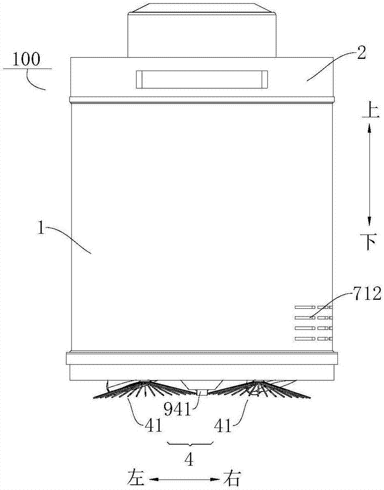
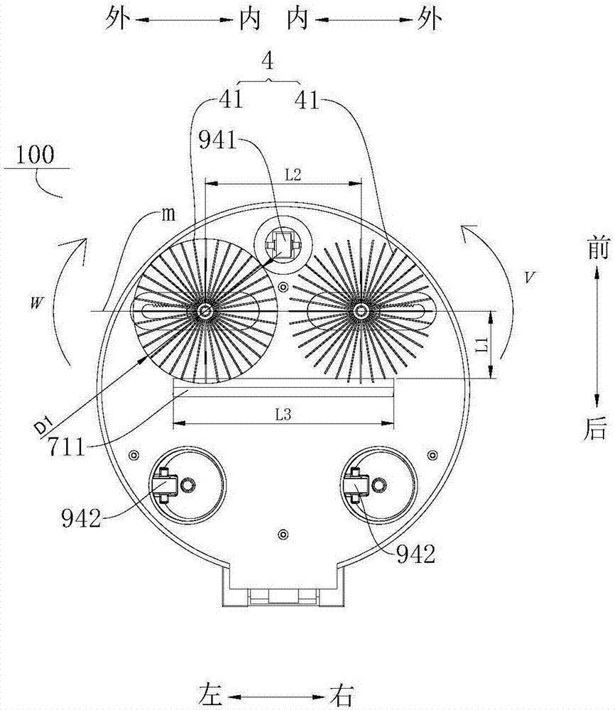
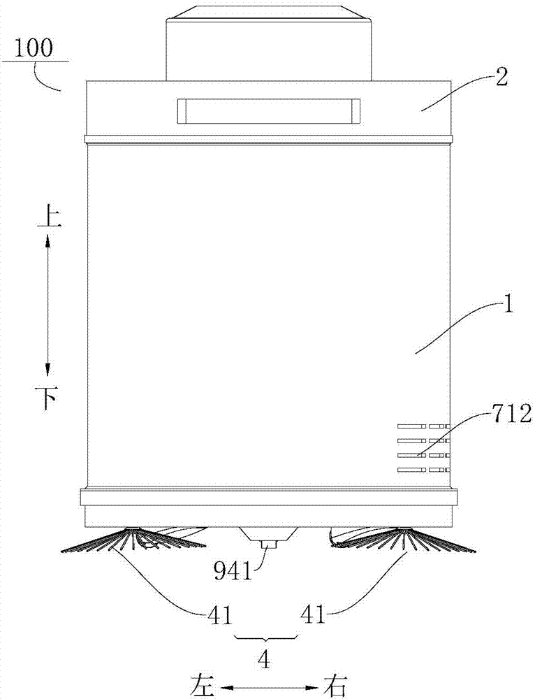
[0139] In some embodiments of the present invention, such as figure 2 , Figure 4 and Figure 15 As shown, the floor brush assembly 4 includes a plurality of spaced apart brush bodies 41 , and the brush bodies 41 are rotatably arranged on the outer bottom wall of the barrel assembly 1 . For example, in figure 1 and figure 2 In the example shown, the ground brush assembly 4 includes two brush bodies 41 spaced apart along the left and right directions, the rotation shafts of the two brush bodies 41 are connected with the outer bottom wall of the barrel assembly 1, and the rotation of the two brush bodies 41 The shafts both extend in the vertical direction, and the two brush bodies 41 are both formed as umbrellas and rotate in the horizontal plane. When the vacuum cleaner 100 is working, the brush body 41 can be in contact with the ground, and the rotation of the brush body 41 can sweep up the dust on the ground so that the vacuum cleaner 100 can absorb the dust, which is beneficial to improving the cleanliness of the ground.
[0140] Certainly, the present invention is not limited thereto, and the ground brush assembly 4 may also include more brush bodies 41 . For example, the ground brush assembly 4 can also include three brush bodies 41, and the connecting line of the rotating shafts of the three brush bodies 41 is triangular. The ground brush assembly 4 can also be four, and the connecting line of the rotating shafts of the four brush bodies 41 is rectangle.
[0141] In some embodiments of the present invention, such as figure 2 , Figure 4 , Figure 11 and Figure 15 As shown, at least one air inlet 711 of the air inlet 71 is close to the outer bottom wall of the barrel assembly 1 . For example, in figure 2 , Figure 4 and Figure 15 In the shown example, the outer bottom wall of the barrel assembly 1 faces the ground, and an air inlet 711 is arranged on the outer bottom wall of the barrel assembly 1, and the air inlet 711 faces the ground. When the vacuum cleaner 100 sucks dust, , the dust can enter the air intake duct 71 through the air intake duct inlet 711 and enter the cup body 51 . When the air inlet 711 is arranged on the outer bottom wall of the barrel assembly 1 , it is convenient for the vacuum cleaner 100 to suck dust.
[0142] Further, as figure 2 , Figure 4 and Figure 15 As shown, the inlet 711 of the air inlet is in the shape of a strip. The strip-shaped air inlet 711 can increase the dust collection area and improve the dust collection efficiency. For example, in figure 2 In the example shown, the inlet 711 of the air inlet is located in the middle of the outer bottom wall of the barrel assembly 1 , the inlet 711 of the air inlet is elongated and extends along the left and right directions, and the floor brush assembly 4 includes two brush bodies 41 , the two brush bodies 41 are located on the front side of the air inlet 711, and the two brush bodies 41 are symmetrically distributed about the central line extending in the front and rear direction of the air inlet 711, and the brush body 41 on the left is along the clockwise direction ( like figure 2 Shown w direction) rotates, the brush body 41 that is positioned at the right side moves counterclockwise (such as figure 2 Shown v direction) rotation, the brush body 41 sweeps the rubbish on both sides to the air inlet 711, which is convenient for the cleaning of the rubbish.
[0143] In some embodiments of the present invention, such as figure 1 , image 3 , Figure 5 , Image 6 and Figure 8 As shown, at least one air outlet 712 of the air outlet 72 is close to the outer peripheral wall of the barrel assembly 1 . As a result, it prevents the air from blowing towards people, and also plays the role of noise reduction and filtering, so that the noise is reduced and the exhausted gas is cleaner. For example, in Figure 8 In the shown example, an air outlet 712 of the air outlet duct 72 is arranged on the lower side of the outer peripheral wall of the barrel assembly 1, and extends along the circumferential direction of the barrel assembly 1, thereby avoiding the Blowing also plays the role of noise reduction and filtering, making the noise lower and the exhaust gas cleaner.
[0144] Further, the air outlet 712 is located at the rear of the barrel assembly 1 and has an included angle α with the rear of the barrel assembly 1, where α≤90°. As a result, when the vacuum cleaner 100 is in use, it is avoided that the air blows directly to people located behind, and the user's comfort level is improved. For example in figure 1 In the example shown, the air outlet 712 is located on the right of the barrel assembly 1 , and the angle α between the centerline of the air outlet 712 and the rear of the barrel assembly 1 is 90°.
[0145] According to some embodiments of the present invention, such as Figure 13 , Figure 79 and Figure 71-Figure 78 As shown, the dust cup assembly 5 includes: a cup body 51 and a cup cover 54. The cup body 51 is in the shape of a single cone and has a dust outlet 52 and an airflow inlet 53. After entering the air duct 71, dust can enter the cup body 51 from the airflow inlet 53 along with the air flow, the dust is separated and settled in the cup body 51, and the dust can flow out of the cup body 51 from the dust outlet 52. The cup cover 54 is covered on the cup body 51 , the cup cover 54 has an air outlet 56 , and the air outlet 56 communicates with the air outlet 72 . The separated air flow in the cup body 51 can flow from the cup body 51 to the cup cover 54 , and then enter the air outlet 72 from the air outlet 56 provided on the cup cover 54 .
[0146] like Figure 13 , Figure 79-Figure 80 and Figure 71-Figure 72 As shown, according to some embodiments of the present invention, the dust cup assembly 5 may further include a cover plate 6 and a filter cotton 67 , and the cover plate 6 may be provided in the cup body 51 and at a position close to the cup cover 54 . The filter cotton 67 can be laid on the cover plate 6 to filter the air flow to the cup cover 54 to prevent dust from entering the cup cover 54 with the air flow, thereby improving the dust collection performance of the dustbin vacuum cleaner 100 .
[0147]According to other embodiments of the present invention, the cup cover 54 is engaged with the cup body 51. For example, the cup cover 54 may be provided with a snap-fit groove, and the cup body 51 may be provided with a snap-fit protrusion. The snap-in protrusions are in one-to-one correspondence, so that the cup body 51 can be snapped onto the cup cover 54 . According to some other embodiments of the present invention, the cup cover 54 is pivotably connected with the bucket cover assembly 2 , so that the operation of the cup cover 54 can be facilitated. According to some other embodiments of the present invention, the cup body 51 is detachably connected to the lid assembly 2 , so that the cleaning and replacement of the cup body 51 can be facilitated.
[0148] According to some other embodiments of the present invention, the cup cover 54 is pivotably connected with the bucket cover assembly 2 , so that the operation of the cup cover 54 can be facilitated.
[0149] In some embodiments of the present invention, such as figure 2 , Figure 4 and Figure 15 As shown, the moving assembly 94 includes a directional wheel 941 and at least one universal wheel 942 , and the directional wheel 941 is located on the front side of the universal wheel 942 . Thereby, the movement of the vacuum cleaner 100 is facilitated, and the free movement of the vacuum cleaner 100 can be realized. For example in figure 2 In the example shown, a directional wheel 941 is provided on the front side of the outer bottom wall of the barrel assembly 1, and two universal wheels 942 spaced apart along the left and right directions are provided on the rear side, and the universal wheels 942 can rotate freely by 360° The combination of the directional wheel 941 and the universal wheel 942 can make the vacuum cleaner 100 move freely indoors.
[0150] In some embodiments of the present invention, the garbage can type vacuum cleaner 100 further includes a battery assembly 98 disposed on at least one of the bucket body assembly 1 and the bucket lid assembly 2 . The battery assembly 98 can supply power for the vacuum cleaner 100, which can make the vacuum cleaner 100 not need to be connected to an external power source, which facilitates the use of the vacuum cleaner 100, and when the vacuum cleaner 100 is used as a trash can, there is no need to consider the storage of the power cord.
[0151] Refer below Figure 1-Figure 87 To describe the trash can type vacuum cleaner 100 according to a specific embodiment of the present invention, it should be understood that the following description is only exemplary and intended to explain the present invention, rather than limiting the present invention.
[0152] like Figure 1-Figure 87 As shown, the garbage can-type vacuum cleaner 100 according to the present invention includes a bucket body assembly 1, a bucket cover assembly 2, a ground brush assembly 4, a dust cup assembly 5, an air duct assembly 7, a driving assembly 93, a moving assembly 94, and a push rod assembly 95 , transmission assembly 3 , drive motor 91 , control assembly 92 , decorative cover 29 , hand-held straw 81 , suction head assembly 8 .
[0153] Among them, such as Figure 12-Figure 14 and Figure 34 As shown, the upper end of the barrel assembly 1 has a barrel opening 142, one of the lid assembly 2 and the barrel assembly 1 is provided with a cover pivot shaft 21, and the other is provided with a cover that cooperates with the cover pivot shaft 21 The body pivot hole 11, the barrel cover assembly 2 is pivotally connected with the barrel assembly 1 to open or close the barrel opening 142. The user can open the lid assembly 2 to throw garbage into the barrel, the barrel assembly 1 can be used as a trash can, and the lid assembly 2 can cover the garbage in the barrel assembly 1, avoiding the exposure of garbage and improving the aesthetics of the user's vision . When the vacuum cleaner 100 does not need to be used, it can be placed in the living room or study room, which is where the trash can is normally placed in the home, and used as a trash can, which can solve the problem that the vacuum cleaner 100 takes up space when it is not in use .
[0154] like Figure 1-Figure 15 As shown, the ground brush assembly 4 is arranged on the outer bottom wall of the barrel assembly 1. When the vacuum cleaner 100 is moved, the ground brush assembly 4 can be in contact with the ground, and the ground brush assembly 4 can sweep up the dust on the ground so that the vacuum cleaner 100 can absorb it. Dust is beneficial to improve the cleanliness of the ground. The dust cup assembly 5 is located on one of the barrel assembly 1 and the lid assembly 2, such as Figure 9 and Figure 11 As shown, the dust cup assembly 5 is provided on the bucket cover assembly 2 , and the dust cup assembly 5 can accommodate the dust absorbed by the vacuum cleaner 100 .
[0155] like Figure 9-Figure 11 , Figure 65 As shown, the air duct assembly 7 is arranged on at least one of the barrel assembly 1 and the lid assembly 2, the air duct assembly 7 defines an air inlet air duct 71 and an air outlet air duct 72, and the air inlet air duct 71 and the air outlet air duct Air duct 72 is all connected with dust cup assembly 5, and dust enters in dust cup assembly 5 through air inlet duct 71, and dust is collected in dust cup assembly 5, and the wind that removes dust is discharged in air outlet duct 72 again.
[0156] like Figure 9 and Figure 11 As shown, the driving assembly 93 is disposed in the lid assembly 2 , and the driving assembly 93 is used to drive the air flow in the air duct assembly 7 to realize the vacuuming of the vacuum cleaner 100 . like figure 2 , Figure 4 and Figure 15 As shown, the moving assembly 94 is disposed at the bottom of the barrel assembly 1 and spaced apart from the ground brush assembly 4 . When the vacuum cleaner 100 needs to be moved, the moving assembly 94 rotates so that the vacuum cleaner 100 can move freely, so as to realize vacuuming in different places.
[0157] like figure 2 , Figure 4 and Figure 15 As shown, the outer bottom wall of the barrel assembly 1 faces the ground, and an air inlet 711 is arranged on the outer bottom wall of the barrel assembly 1, and the air inlet 711 faces the ground. When the vacuum cleaner 100 sucks dust, the dust can It enters into the air intake duct 71 through the air intake duct inlet 711 and enters into the dust cup assembly 5 . When the air inlet 711 is arranged on the outer bottom wall of the barrel assembly 1 , it is convenient for the vacuum cleaner 100 to suck dust.
[0158] Further, as figure 2 , Figure 4 and Figure 15 As shown, the inlet 711 of the air inlet is located in the middle of the outer bottom wall of the barrel assembly 1. The inlet 711 of the air inlet is elongated and extends along the left and right directions. On the front side, the two brush bodies 41 are distributed symmetrically with respect to the central line extending in the front and back direction of the air inlet 711, and the brush body 41 on the left is clockwise (such as figure 2 Shown w direction) rotates, the brush body 41 that is positioned at the right side moves counterclockwise (such as figure 2 Shown v direction) rotation, the brush body 41 sweeps the rubbish on both sides to the air inlet 711, which is convenient for the cleaning of the rubbish.
[0159] The pipe section of the air inlet duct 71 near the inlet 711 of the air inlet duct is a telescopic pipe. combine Figure 55 and Figure 60 As shown, by setting the pipe section of the air inlet duct 71 close to the inlet 711 of the air inlet duct as a telescopic pipe section, it is convenient for the garbage can-type vacuum cleaner 100 to adjust its shape accordingly under different working environment requirements.
[0160] like Figure 8 As shown, an air outlet 712 of the air outlet duct 72 is arranged on the lower side of the outer peripheral wall of the barrel assembly 1, and extends along the circumferential direction of the barrel assembly 1, thereby avoiding blowing against people, and at the same time It also plays the role of noise reduction and filtering, making the noise lower and the exhaust gas cleaner. like figure 1 As shown, the air outlet 712 is located on the right of the barrel assembly 1, and the angle α between the center line of the air outlet 712 and the rear of the barrel assembly 1 is 90°.
[0161] like Figure 5 , Figure 7 and Figure 14 As shown, one end of the suction head assembly 8 communicates with the air inlet duct 71 , and the other end of the suction head assembly 8 communicates with the inlet 711 of the air inlet duct. When the vacuum cleaner 100 cleans the ground, the dust on the ground can enter the suction head assembly 8 through the air inlet 711, then enter the air intake duct 71, and then enter the dust cup assembly 5; when the vacuum cleaner 100 cleans the sofa coffee table, etc. , the end of the suction head assembly 8 connected to the air inlet 711 can be pulled out, and some cleaning accessories (such as a suction head with a specific cleaning function) can be equipped to clean the sofa coffee table, etc., thereby facilitating the cleaning of the suction head. storage, and can simplify the structure of the vacuum cleaner 100 at the same time.
[0162] Further, as Figure 5 , Figure 7 and Figure 14 As shown, a hand-held suction pipe 81 is provided between the suction head assembly 8 and the air inlet duct 71 . The suction head assembly 8 can be arranged at the end of the hand-held straw 81 and communicate with the hand-held straw 81 , and the hand-held straw 81 can be held by hand for cleaning. In addition, the hand-held suction pipe 81 can include a hand-held part and a telescopic hose, one end of the hand-held part is connected to the suction head assembly 8, one end of the telescopic hose is connected to the other end of the hand-held part, and the other end of the telescopic hose is communicated with the air inlet duct 71 . When the telescopic hose is not in use, it can be shrunk inside the barrel assembly 1. When the suction head assembly 8 is pulled out to clean the sofa and tea table, etc., the telescopic hose extends out of the barrel assembly 1 so that the suction head assembly 8 can be freely Mobile, no need to move the barrel assembly 1, to meet the cleaning needs of users.
[0163] like Figure 40 As shown, one end of the hand-held straw 81 (the end of the hand-held straw 81 communicating with the air inlet duct 71 ) is connected to the upper part of the barrel assembly 1 . Thus, the structure of the vacuum cleaner 100 can be made more compact and reasonable, which is convenient for users to store, and meanwhile the aesthetics of the vacuum cleaner 100 can also be improved.
[0164] like Figure 5 and Figure 40 As shown, the outer peripheral wall of the bucket assembly 1 is provided with a storage groove 15 extending in the up and down direction, and the hand-held straw 81 is arranged in the storage groove 15. Part of the structure of the hand-held straw 81 is hidden in the barrel assembly 1, and part of the structure is exposed. Outside the barrel assembly 1, when the sofa or coffee table needs to be cleaned, the suction head assembly 8 can be pulled out, and the hand-held suction pipe 81 can be extended. At this time, the suction head assembly 8 can be directly used to clean the sofa or coffee table, or the suction head assembly can be 8 Use with some conventional small accessories to make the use effect better.
[0165] Further, a straw limiting portion 151 is provided on the receiving groove 15, and the straw limiting portion 151 is adapted to engage with the other end of the handheld straw 81 (the end where the handheld straw 81 is connected to the suction head assembly 8). Thus, the hand-held straw 81 can be fixed in the storage slot 15 , preventing the hand-held straw 81 from slipping out of the storage slot 15 and affecting the use of the user.
[0166] like figure 2 , Figure 4 and Figure 15 As shown, the moving assembly 94 includes a directional wheel 941 and at least one universal wheel 942 , and the directional wheel 941 is located on the front side of the universal wheel 942 . The front side of the outer bottom wall of the barrel assembly 1 is provided with a directional wheel 941, and the rear side is provided with two universal wheels 942 spaced apart along the left and right directions. The universal wheels 942 can rotate freely at 360°. Combined with the wheels 942, the vacuum cleaner 100 can be moved indoors arbitrarily.
[0167] The garbage can type vacuum cleaner 100 also includes a battery assembly 98 disposed on at least one of the bucket body assembly 1 and the bucket cover assembly 2 . The battery assembly 98 can supply power for the vacuum cleaner 100, which can make the vacuum cleaner 100 not need to be connected to an external power source, which facilitates the use of the vacuum cleaner 100, and when the vacuum cleaner 100 is used as a trash can, there is no need to consider the storage of the power cord.
[0168] like Figure 57-Figure 61 As shown, the push rod assembly 95 is connected with the barrel assembly 1 . Thus, the user can conveniently push the dustbin-type vacuum cleaner 100 to move through the push rod assembly 95, so that the dust removal work is more flexible and convenient. When the trash can-type vacuum cleaner 100 is performing dust removal work, the user uses the push rod assembly 95 to push the trash-can-type vacuum cleaner 100 to move. During the movement of the trash-can-type vacuum cleaner 100, the floor brush assembly 4 rotates to clean the dust, and sucks the dust-entrained airflow into the air. Air duct 71, the airflow entraining dust enters into the dust cup assembly 5 through the air inlet duct 71, the dust is separated and settled in the dust cup assembly 5, and finally, the airflow that removes dust is discharged from the air outlet duct 72 to complete Dust extraction with trash can vacuum cleaner 100.
[0169]At least one of the barrel assembly 1 and the push rod assembly 95 is provided with a push rod installation part, thus, when the trash can type vacuum cleaner 100 is used as a trash can, the push rod assembly 95 can be stowed and passed through the push rod installation part Securely fixed. There may be a plurality of push rod installation parts spaced apart along the length direction of the push rod assembly 95 to fix the push rod assembly 95 to the barrel assembly 1 , thereby enhancing the stability and reliability of the push rod assembly 95 .
[0170] Further, at least one of the plurality of push rod installation parts is a clamping part. In this way, the processing and manufacturing of the push rod mounting portion is facilitated, thereby reducing the production cost and facilitating the fixing of the push rod assembly 95 .
[0171] like Figure 59-Figure 61 As shown, the barrel assembly 1 is rotatable relative to the floor brush assembly 4 . It can be understood that when the garbage can type vacuum cleaner 100 cleans up the dust on the ground, the barrel assembly 1 can be rotated to Figure 60 The state shown in , in order to facilitate the user to push the trash can type vacuum cleaner 100 to carry out the dust removal and cleaning work; Body assembly 1 is rotated to as Figure 61 In the state shown in , the overall height of the garbage can-type vacuum cleaner 100 can be further lowered so as to smoothly carry out the dust removal work.
[0172] like Figure 6-Figure 9 As shown, the push rod assembly 95 is connected to the barrel assembly 1 and the lower end of the push rod assembly 95 is pivotally connected to the lower end of the barrel assembly 1 . Therefore, when the trash can-type vacuum cleaner 100 is used as a trash can, the push rod assembly 95 can be rotated close to the barrel assembly 1 and stored, so as to reduce the occupied space. Moreover, the user can rotate the push rod assembly 95 to a comfortable angle to carry out the dust removal work according to the height and usage habits, thereby making the dust removal work more convenient and comfortable.
[0173] like Figure 58-Figure 61 As shown, the push rod assembly 95 of the garbage can type vacuum cleaner 100 can be a retractable push rod. Thus, when the trash can type vacuum cleaner 100 is used as a trash can, the push rod assembly 95 can be put away to reduce the occupied space of the trash can type vacuum cleaner 100; The rod assembly 95 is pulled out to facilitate the pushing of the trash can type vacuum cleaner 100 for dust removal.
[0174] Further, as Figure 5-Figure 9 As shown, the push rod assembly 95 can be set as a three-section telescopic rod, and the total length of the stretched rod can be set to about 110 cm. When performing dust removal work, the user can stretch the push rod assembly 95 to different lengths according to his own height and usage habits, and rotate it to adjust to different angles, so as to perform dust removal conveniently and comfortably. Moreover, when the trash can-type vacuum cleaner 100 is used as a trash can, the push rod assembly 95 can be compressed and packed, and screwed to the rear of the barrel body assembly 1 to reduce the occupied space of the trash-can-type vacuum cleaner 100 and improve the The appearance of the garbage can type vacuum cleaner 100 is aesthetically pleasing. Of course, the push rod assembly 95 can also be set to have multiple sections, and the total length of the telescopic rod can also be set differently according to different requirements.
[0175] like Figure 16-Figure 19 As shown, the driving end 311 of the transmission assembly 3 is arranged on the bucket body assembly 1, and the execution end 321 of the transmission assembly 3 is connected with the bung lid assembly 2 to drive the bung lid assembly 2 to rotate, so that the bung lid assembly can be opened by driving the driving end 311 2. For example, the driving end 311 can be stepped on with a foot to open the bucket lid. When the user needs to throw away the rubbish, it will be very inconvenient to open the lid assembly 2 by hand, and step on the driving end 311 to open the lid assembly 2, and when the foot is removed, the lid assembly 2 will automatically close , which is convenient for users to use.
[0176] like Figure 17 and Figure 19 As shown, the driving end 311 is located at the bottom of the barrel assembly 1 . The free end of the driving end 311 exceeds the outer peripheral wall of the barrel assembly 1 . Therefore, it is convenient to step on the driving end 311 with a foot to drive the bucket lid assembly 2 to rotate. like Figure 17 and Figure 19 As shown, the transmission assembly 3 includes a transmission pivot rod 31 and a transmission connection rod 32. The transmission pivot rod 31 can be a lever structure. Located in the barrel assembly 1, one end of the transmission pivot rod 31 beyond the outer peripheral wall of the barrel assembly 1 is configured as a driving end 311, and one end of the transmission pivot rod 31 has a bent portion, and the bent portion is formed as the driving end 311 . One end of the transmission connecting rod 32 is connected to the other end of the transmission pivot rod 31 , the other end of the transmission connecting rod 32 is connected to the bung assembly 2 , and the other end of the transmission connecting rod 32 is configured as an actuating end 321 . When stepping down on the driving end 311 with your feet, the other end of the transmission pivot rod 31 moves upwards, thereby driving the transmission connecting rod 32 to move upwards to drive the bucket cover assembly 2 to rotate, so that the bucket body opening 142 is exposed outside, which is convenient for the Rubbish is thrown in the staving assembly 1.
[0177] like Figure 19 As shown, the part where the upper end of the transmission connecting rod 32 is connected to the bucket cover assembly 2 is close to the part where the bucket cover assembly 2 is connected to the bucket body assembly 1 . Thus, when the lid assembly 2 is rotated to the open position, the transmission connecting rod 32 can be prevented from blocking the opening 142 of the bucket body and affecting the throwing of garbage into the bucket body assembly 1 .
[0178] like Figure 17 , Figure 19 and Figure 34 As shown, the driving assembly 93 is close to the part of the lid assembly 2 connected with the barrel assembly 1 . Specifically, the driving assembly 93 is arranged above the cover pivot shaft 21 of the bucket body assembly 1 and the bucket cover assembly 2 and the execution end 321. Because the weight of the driving assembly 93 is relatively large, the center of gravity of the driving assembly 93 is placed on the bucket assembly. 1 and the lid pivot shaft 21 of the lid assembly 2 and the position of the actuator end 321 can reduce the opening force, just step on the driving end 311 lightly, the lid assembly 2 can be opened, and the foot is removed, and the lid Component 2 and can be turned off automatically.
[0179] like Figure 20-Figure 23 As shown, the driving motor 91 is a stepping motor, and the driving motor 91 is connected with the lid assembly 2 to drive the lid assembly 2 to move. The driving motor 91 is provided at the lid pivot shaft 21 of the lid assembly 2 and the barrel assembly 1. To drive the lid assembly 2 to rotate around the pivot shaft 21 of the lid body. The control component 92 is connected in communication with the drive motor 91 to control the start or stop of the drive motor 91 . Thus, the drive motor 91 can be activated by the control assembly 92, thereby driving the lid assembly 2 to rotate, and the lid assembly 2 is opened without directly opening the lid assembly 2 by hand, which is convenient for users to use.
[0180] like Figure 20 and Figure 21 As shown, the control component 92 is an infrared sensor, and the infrared sensor is connected to the drive motor 91 in communication. The infrared sensor can sense objects around it. When the infrared sensor senses that there are objects around it, it can control the drive motor 91 Action, and drive bung assembly 2 to open.
[0181] like Figure 20 and Figure 21 As shown, two infrared sensors are arranged on the upper end surface of the lid assembly 2 near the front side, and the two infrared sensors are arranged at intervals along the left and right directions, which can increase the sensing range of the infrared sensors. As long as there is an object close to the infrared sensor, the driving motor 91 will automatically turn on, the motor shaft 911 of the driving motor 91 will rotate clockwise, and the motor shaft 911 of the driving motor 91 will also drive the cover pivot shaft 21 of the lid assembly 2 together. in a clockwise direction (e.g. Figure 23 Rotate in the clockwise direction u) as shown, and the bung assembly 2 is opened. After opening to an angle of 45°, the driving motor 91 will automatically stop rotating, and will keep this angle still. No matter how it shakes in front of the infrared sensor at this moment, the driving The motor 91 will not rotate again, and the lid assembly 2 will be in the open state. After putting away the garbage, there is no need to manually close the lid assembly 2. When the infrared sensor does not detect any object for 5 seconds, the drive motor 91 will Start again, at this time the motor shaft 911 of the drive motor 91 will rotate counterclockwise, and drive the lid pivot shaft 21 of the bung assembly 2 to rotate together, close the bung assembly 2, after the bung assembly 2 is closed, drive the motor 91 automatically stops working.
[0182] It should be noted that when the trash can-type vacuum cleaner 100 is used as a trash can, the switch 97 of the vacuum cleaner 100 is in the off state, and at this time the infrared sensor and the drive motor 91 are connected; After turning on the switch 97 of the vacuum cleaner 100, the infrared sensor will be automatically disconnected from the drive motor 91. At this time, if there is an obstacle close to the infrared sensor, the drive motor 91 will not be activated to cause the lid to be opened. In addition, the power source of the infrared sensor and the driving motor 91 can be the same as the power source of the vacuum cleaner 100, and both can be the battery assembly 98 in the machine.
[0183] like Figure 20 and Figure 21 As shown, a lid opening button 22 is also provided on the upper surface of the lid assembly 2 , and the lid opening button 22 is connected to the driving motor 91 in communication. Press the lid opening button 22, the drive motor 91 starts, and the lid assembly 2 is opened. After throwing away the garbage, the lid assembly 2 will also be automatically closed; if both infrared sensors are broken, press the lid opening button 22 , can also open the lid assembly 2, but closing the lid assembly 2 also needs to be done manually. The purpose of designing the lid opening button 22 is to enable the lid assembly 2 to pass through the same when the infrared sensor is broken. The driving motor 91 realizes the function of automatic opening.
[0184] like Figure 25-Figure 33 As shown, the barrel assembly 1 is provided with two lid stoppers 23, the two lid stoppers 23 are spaced apart, and protrude toward the side of the barrel assembly 1, and the side of the barrel assembly 2 faces the barrel One side of the assembly 1 is provided with a raised lid stopper 24. In the direction from top to bottom, the cross-sectional area of the lid stopper 24 gradually decreases, and the outline of the lid stopper 24 is smooth Transition, where the cross-sectional area of the bung stopper 24 is the smallest, that is, the lower end of the bung stopper 24 is provided with a raised structure, and the sidewall of the raised structure is suitable for cooperating with the bung stopper 23 to limit the bung Opening angle of component 2.
[0185] When the lid assembly 2 is opened to a certain angle, the lid assembly 2 will first cooperate with the lid stopper 23 close to it, and when the user opens it a little further, the raised part will interfere with the lid stopper 23 Cooperate, the raised part is in full contact with the lid stopper 23, the lid assembly 2 can be kept open, if you want to open the lid assembly 2 a little bigger, you can continue to open the lid assembly 2 upwards, the maximum can be opened to the convex The position where the lifting position cooperates with the bung stopper 23 away from it, at this moment, the opening angle of the bung assembly 2 has reached the maximum, and cannot be opened further. The raised portion is defined between the two lid stoppers 23, and the lid assembly 2 can remain motionless.
[0186] It should be noted that when the lid stopper 24 cooperates with the lid stopper 23 close to it, the opening angle of the lid can be limited to 45°. At this time, throwing rubbish into the barrel assembly 1 has little impact; When the bung stopper 24 cooperates with the bung stopper 23 away from it, the opening angle of the bung assembly 2 can be limited to 60°, at this moment, the dust cup assembly 5 can be taken out from the inside of the bucket assembly 1 . The present invention takes two angles of 45° and 60°, and the present invention can also set other angles according to actual needs.
[0187] like Figure 25-Figure 33 As shown, during the opening process of the bung assembly 2, the bung stopper 23 that first contacts with the bung stopper 24 is formed into a cylindrical shape, and the raised portion on the bung stopper 24 is in contact with the columnar bung stopper. The outer peripheral wall of the positioning member 23 cooperates, thus, it is convenient for the raised part to cross over the columnar bung stopper 23 and cooperate with the rear contact bung stopper 23 . In addition, during the opening process of the bung assembly 2, the bung stopper 23 in contact with the bung stopper 24 is formed into a rectangular column, and the side wall of the rectangular column cooperates with the protruding part to prevent the protruding part from continuing to cross the rectangular column. The columnar lid stopper 23 affects the user's use.
[0188] like Figure 9 , Figure 11 and Figure 34As shown, the driving assembly 93 is used to drive the air flow in the air duct assembly 7 to realize the vacuuming of the vacuum cleaner 100 . The driving assembly 93 is arranged on the bung assembly 2, and the bung assembly 2 adopts an overall design, and there is no gap and part joint surface at the position where the driving assembly 93 is placed. If water is sprinkled on the bung assembly 2 during use, Water can only flow to the ground along the side of the bung assembly 2, and there is no way to be sucked into the drive assembly 93, which avoids the phenomenon that the user causes the drive assembly 93 to burn out due to improper use. In addition, the dust cup assembly 5 and the driving assembly 93 are both arranged on the bucket cover assembly 2, and the dust cup assembly 5 and the driving assembly 93 are arranged in parallel, so that the distance of the air duct can be reduced, so as to reduce suction loss.
[0189] like Figure 13 , Figure 79 and Figure 71-Figure 78 As shown, the dust cup assembly 5 includes a cup body 51 and a cup cover 54 . The cup body 51 can be in the shape of a single cone. The cup body 51 can be provided with a dust outlet 52 and an airflow inlet 53 . The airflow inlet 53 communicates with the air inlet duct 71 , and the airflow outlet 56 communicates with the air outlet duct 72 .
[0190] After the dust-entrained airflow passes through the air inlet duct 71, it can enter the cup body 51 from the airflow inlet 53. After the dust and the airflow are separated, the dust can flow out of the cup body 51 from the dust outlet 52, and the airflow that removes most of the dust can flow out of the cup body 51. The body 51 flows to the cup cover 54 and enters the air outlet 72 from the air outlet 56 provided on the cup cover 54 .
[0191] like Figure 73-Figure 80 As shown, the airflow inlet 53 may include a plurality of round holes, the round holes can allow wind and small particles of dust to pass through, and can block the passage of large particles of dust, so as to achieve preliminary separation of wind and dust. It should be noted that the "circular hole" mentioned here is just a structural expression, and the circular hole may be in any shape, for example, square, rectangular or triangular. like Figure 71-Figure 80 Shown, dust outlet 52 can be located at the bottom of cup body 51 (as Figure 76 shown below). Further, the central axis of the dust outlet 52 can be parallel to the central axis of the barrel opening 142 , so that the dust can flow out from the cup 51 conveniently.
[0192] like Figure 71-Figure 80 As shown, there is a main channel 60 in the cup body 51, the main channel 60 runs through the cup body 51, the main channel 60 is single cone, and the cross-sectional area of the main channel 60 is from top to bottom (as Figure 76 shown in the up and down directions) decrements. One end of the cup body 51 near the cup cover 54 is provided with a plurality of airflow guide channels 58 , one end of the airflow guide channels 58 can communicate with the main channel 60 , and the other end of the airflow guide channels 58 can communicate with the airflow inlet 53 . In the direction from the radially outer side to the radially inner side of the cup body 51, the airflow guiding channel 58 deviates toward one of the clockwise direction and the counterclockwise direction of the cup body 51, for example, the airflow guiding channel 58 is along the direction of the main channel 60. Tangentially counterclockwise (eg Figure 78 Shown in direction a) extends. The airflow can enter the airflow guiding channel 58 from the airflow inlet 53 , and then enter the main channel 60 from the airflow guiding channel 58 .
[0193] Further, a plurality of surrounding plates 59 may be provided inside the cup body 51 , and the airflow guiding channel 58 may be defined by the surrounding plates 59 . like Figure 67 and Figure 76 As shown, the cup body 51 is provided with a plurality of surrounding plates 59 to define an airflow guiding channel 58 . Therefore, the structure of the dust cup assembly 5 can be simplified, and the manufacturing process can be simplified, thereby reducing the production cost.
[0194] like Figure 73-Figure 80 As shown, the outer wall of the cup body 51 can be provided with an air inlet baffle 57, and the air inlet baffle 57 is positioned under the airflow guiding channel 58 (as shown in FIG. Figure 76 shown below). Further, the cup cover 54 can be connected with the inner peripheral wall of the bung cover assembly 2, the air inlet partition 57 can be against the inner peripheral wall of the bung cover assembly 2, and the air inlet partition 57, the cup cover 54 and the inner peripheral wall of the bung cover assembly 2 A chamber 66 is formed, and the other end of the airflow guide channel 58 communicates with the chamber 66 through the cup wall of the cup body 51 .
[0195] After the air flow enters the chamber 66 from the air inlet 53, it can flow around the peripheral wall of the part of the cup body 51 in the chamber 66, for example, counterclockwise around the part of the peripheral wall of the cup body 51 in the chamber 66 (such as Figure 78 shown in the v1 direction) flow. Subsequently, the airflow enters the main passage 60 through a plurality of airflow guiding passages 58, and flows around the inner peripheral wall of the main passage 60. Since the airflow guiding passage 58 extends counterclockwise along the tangential direction of the main passage 60, the The flow direction of the airflow is opposite to the flow direction of the airflow on the outer peripheral wall of the cup body 51, for example, clockwise around the inner peripheral wall of the main passage 60 (such as Figure 78 Shown v2 direction) flow, so that the rotational inertia of the dust can be reduced.
[0196] Since the main channel 60 is single-cone, the dust-containing airflow will rotate downward with the main channel 60, and the dust will fall and flow out of the cup body 51 from the dust outlet 52. The airflow velocity will gradually increase, and the airflow will suddenly rise after reaching a certain velocity Flow out from the cup body 51, and then realize the further separation of dust and wind.
[0197] like Figure 13 , Figure 79-Figure 80 and Figure 71-Figure 72 As shown, the dust cup assembly 5 can also include a cover plate 6 and a filter cotton 67, the cover plate 6 can be covered on the cup body 51 and connected with the inner peripheral wall of the bucket lid assembly 2, and the filter cotton 67 can be laid on the cover plate 6 To filter the air flow to the cup lid 54 . Thus, the filter cotton 67 can prevent dust from entering the cup cover 54 along with the airflow, thereby improving the dust collection performance of the garbage can-type vacuum cleaner 100 . For example, the filter cotton 67 can be flocculent cotton, because the cotton has small gaps, it can block most of the dust and foreign matter, and the blocking effect is good, easy to obtain, and low in cost.
[0198] like Figure 80 As shown, a seal 55 may be provided between the cover plate 6 and the inner peripheral wall of the bung assembly 2, thereby preventing dust from flowing into the cup cover 54 from the gap between the cover plate 6 and the inner peripheral wall of the bung assembly 2, The sealing performance of the trash can type vacuum cleaner 100 can be improved. Further, as Figure 74 As shown, the outer peripheral wall of the cover plate 6 can be provided with a receiving groove 64, and the sealing member 55 can be embedded in the receiving groove 64, which can not only improve the sealing performance of the dust cup assembly 5, but also improve the integration of the dust cup assembly 5. and aesthetics.
[0199] like Figure 80 and Figure 71-Figure 72 As shown, the cover plate 6 can include a flat plate portion 61 and a raised portion 62, the raised portion 62 can be arranged on the side of the flat plate portion 61 close to the cup body 51, and the raised portion 62 can extend into the cup body 51, the flat plate The portion 61 can be covered on the cup body 51 , and the periphery of the flat portion 61 can abut against the inner wall of the cup cover 54 . The cover plate 6 has a through hole, the through hole passes through the raised portion 62 and the flat plate portion 61 and communicates with the main passage 60 in the cup body 51 , the air flow can flow into the cup cover 54 from the cup body 51 through the through hole on the cover plate 6 Inside. The filter cotton 67 can be laid on the flat part 61 to filter the airflow to the cup cover 54 to prevent dust from entering the cup cover 54 with the airflow, thereby improving the dust collection performance of the dustbin vacuum cleaner 100 .
[0200] A seal 55 may be provided between the flat plate portion 61 of the cover plate 6 and the inner peripheral wall of the cup cover 54, thereby improving the sealing performance of the dust cup assembly 5 and preventing dust from passing through the gap between the cover plate 6 and the inner peripheral wall of the cup cover 54. The place flows into the cup cover 54, thereby improving the dust collection performance of the dustbin type vacuum cleaner 100. Further, the outer peripheral wall of the flat plate portion 61 can be provided with a receiving groove 64, and the sealing member 55 can be embedded in the receiving groove 64, which can not only improve the sealing performance of the dust cup assembly 5, but also improve the integration of the dust cup assembly 5. and aesthetics.
[0201] like Figure 71-Figure 80 As shown, the periphery of the flat plate 61 can be provided with an edge extension 65, and the edge extension 65 extends along the part of the cup cover 54 that is in contact with the flat plate 61, so as to prevent the air from flowing from the periphery of the cover plate 6 to the cup cover 54. . Further, as Figure 72 As shown, a handle portion 63 can be provided on the side of the plate portion 61 close to the lid assembly 2 , so that the cover plate 6 can be easily removed from the cup body 51 or installed on the cup body 51 .
[0202] Further, the cup cover 54 is engaged with the cup body 51. For example, the cup cover 54 may be provided with a snap-fit groove, and the cup body 51 may be provided with a snap-fit protrusion, and the snap-fit groove and the snap-fit protrusion are one by one Correspondingly, the cup body 51 can be snapped onto the cup cover 54 . The cup cover 54 is pivotally connected with the bucket cover assembly 2, so that the operation of the cup cover 54 can be facilitated. The cup body 51 is detachably connected with the bucket cover assembly 2, so that the cleaning and replacement of the cup body 51 can be facilitated.
[0203] like Figure 79-Figure 80 As shown, the bung assembly 2 includes a dust cup bottom cover 28 and an ash pouring channel 27, the ash pouring channel 27 is arranged on the bung cover assembly 2, and the ash pouring channel 27 has an ash pouring outlet 271 and an ash pouring inlet 272, and the dust cup bottom cover 28 is pivotally connected with the bucket cover assembly 2, so that the dust outlet 52 can be opened or closed by turning the dust cup bottom cover 28. The dust cup assembly 5 can be arranged on the bucket cover assembly 2, and the dust cup assembly 5 has a dust outlet 52, and the dust outlet 52 communicates with the ash dump inlet 272. The dust in the dust cup assembly 5 can flow out from the dust outlet 52. Since the dust outlet 52 communicates with the ash inlet 272, the dust can enter an end of the ash outlet 27 near the ash inlet 272 from the ash inlet 272.
[0204] Wherein, when the bung assembly 2 closed the bucket opening 142, the dust cup bottom cover 28 closed the ash outlet 271, and the ash channel 27 was isolated from the bucket assembly 1; when the bung assembly 2 opened the bucket opening 142, the dust cup Bottom cover 28 is due to self gravity, and dust cup bottom cover 28 can be far away from ash outlet 271, thereby opens ash outlet 271, and the dust in the ash channel 27 can flow out from ash outlet 271.
[0205] like Figure 79-Figure 80 As shown, the ash dumping channel 27 extends in the horizontal plane, and when the lid assembly 2 opens the barrel body opening 142, the ash dumping channel 27 gradually slopes downward toward the ash dumping outlet 271 . It can be understood that when the bung assembly 2 closed the bucket opening 142, the ash channel 27 was in the horizontal plane (such as Figure 23 The plane where the shown left and right direction is located) extends, and the ash inlet 272 and the ash outlet 271 are in the up and down direction (such as Figure 23 The distance in the up-down direction shown) is zero. When the bung assembly 2 opened the staving opening 142, the ash passage 27 rotated with the bung assembly 2, and the ash inlet 272 and the ash outlet 271 were in the up and down direction (as Figure 13 The distance on the shown up and down direction) is increasing, and the ash outlet 271 is located below the ash inlet 272 (such as Figure 13 shown below).
[0206] like Figure 82 As shown, the angle between the plane where the ash dumping outlet 271 is located and the extending direction of the ash dumping channel 27 is ε, and the range of ε can be (0°, 90°)∪(90°, 180°). It can be understood that the ash dump outlet 271 adopts an oblique design, which can facilitate the flow of dust from the ash dump outlet 271 .
[0207] Further, the range of ε may be (25°, 90°). When the lid assembly 2 opens the barrel opening 142, the dust cup bottom cover 28 can be far away from the ash outlet 271, and the ash outlet 271 adopts an oblique design, which can increase the plane where the ash outlet 271 is located and where the dust cup bottom cover 28 is located. The angle between the planes can facilitate the flow of dust from the ash pouring channel 27, for example, ε can be set to 45°.
[0208] like Figure 81 As shown, the edge of the dust cup assembly 5 at the dust outlet 52 engages with the edge of the ash dumping channel 27 at the ash dumping inlet 272 , so that the dust outlet 52 can communicate with the dust dumping inlet 272 .
[0209] like Figure 85As shown, the wall surface of the dust cup bottom cover 28 facing the ash outlet 271 is a guide slope 281. After the dust flows out from the ash outlet 271, it can be guided into the bottom of the barrel assembly 1 through the guide slope 281, thereby avoiding The dust flows and splashes to the inner wall of the barrel assembly 1 or the outside of the barrel assembly 1, affecting user experience.
[0210] like Figure 83 As shown, the ash pouring passage 27 extends along the radial direction of the barrel opening 142. It can be understood that the ash pouring passage 27 extends in a straight line, and the extending direction of the ash pouring passage 27 is parallel to the radial direction of the barrel opening 142. Dust can flow out from the ash channel 27 more easily.
[0211] like Figure 83 As shown, the ash outlet 271 is close to the part of the lid assembly 2 connected to the barrel assembly 1 . In this way, the setting of the bottom cover 28 of the dust cup can be facilitated, and the guiding of the dust by the guiding slope 281 can be facilitated, so as to prevent the dust from splashing to the inner wall of the barrel assembly 1 .
[0212] Specifically, the dust cup bottom cover 28 includes a main body 284 and two flanges 285, the main body 284 is connected to one of the bucket cover assembly 2 and the bucket body assembly 1 to open or close the ash outlet 271, the main body 284 width The two side edges in the direction are folded toward the ash dumping channel 27 to form a flanged portion 285 , and the part of the main body 284 between the two flanged portions 285 is opposite to the ash dumping outlet 271 .
[0213] It can be understood that the shape of the dust cup bottom cover 28 is similar to that of the dustpan. The dust cup bottom cover 28 includes a main body 284 and two flanges 285 on both sides of the main body 284. The two flanges 285 are all located on the side of the main body part 284 close to the ash outlet 271, and the two flange parts 285 are located on the width direction of the main body part 284 (such as Figure 85 front-to-back orientation shown). The part between the two flanges 285 on the main body 284 is suitable for opening or closing the ash outlet 271. When the main body 284 closes the ash outlet 271, the ash outlet 271 can be located between the main body 284 and the two flanges. In the groove formed by the part 285; when the main part 284 opens the ash outlet 271, the dust cup bottom cover 28 can guide the dust from the groove to the barrel assembly 1.
[0214] It should be noted that the specific shapes of the main body portion 284 and the flange portion 285 are not specifically limited, for example, the body portion 284 may be rectangular or semi-elliptical, and the flange portion 285 may be rectangular or trapezoidal. Further, the angle range between the extension direction of the flange portion 285 and the plane where the main body portion 284 is located may be (0°, 90°)∪(90°, 180°). Furthermore, the angle range between the extension direction of the flange portion 285 and the plane where the main body portion 284 is located may be (90°, 115°), for example, as Figure 85 As shown, the included angle between the extending direction of the flange portion 285 and the plane where the main body portion 284 is located is 90°.
[0215] like Figure 12-Figure 14 As shown, the upper end of the barrel assembly 1 has a first limiting member 12 , and the bottom cover 28 of the dust cup is provided with a second limiting member 282 and a third limiting member 283 . The first limiting member 12 can be arranged on the barrel assembly 1 at a position close to the bottom cover 28 of the dust cup, and the second limiting member 282 can be arranged on the side of the bottom cover 28 of the dust cup close to the first limiting member 12, When the lid assembly 2 closes the barrel opening 142, the first stopper 12 can be offset against the second stopper 282 so that the dust cup bottom cover 28 closes the ash dump outlet 271, and the ash dump channel 27 is isolated from the barrel assembly 1 The third limiter 283 can be arranged on the side of the dust cup bottom cover 28 away from the ash outlet 271. When the bucket cover assembly 2 opens the barrel opening 142, the dust cup bottom cover 28 will close the bottom of the dust cup due to its own gravity. The cover 28 can be away from the ash outlet 271, and the third stopper 283 can rotate with the bottom cover 28 of the dust cup to the position against the bucket cover assembly 2, so that the bottom cover 28 of the dust cup can be fixed and stop rotating, so that it can Guide the dust flowing out of the dust outlet 271 into the barrel assembly 1 .
[0216] Wherein, the first limiting member 12 , the second limiting member 282 and the third limiting member 283 may be limiting protrusions. It should be noted that there is no specific limitation on the shape of the position-limiting protrusion, and the position-limiting protrusion may be triangular, polygonal, or elliptical.
[0217] The first limiting part 12 can be located on the inner peripheral wall of the barrel assembly 1, so that it can cooperate with the setting of the dust cup bottom cover 28 to easily realize the first limiting part 12 and the second limiting part on the dust cup bottom cover 28. 282 abutments. The third stopper 283 is located close to the part of the bottom cover 28 of the dust cup connected to the lid assembly 2, which not only simplifies the setting of the third stopper 283, but also improves the connection between the third stopper 283 and the lid assembly 2. The abutment stability of the dust cup bottom cover 28 can be improved.
[0218] like Figure 87 As shown, the angle between the surface of the dust cup bottom cover 28 facing the ash outlet 271 and the direction in which the ash outlet 27 extends is β, and when the lid assembly 2 closes the barrel opening 142, the range of β is (25°, 90°). For example, β can be 95°. During the process of opening the barrel opening 142 by the barrel lid assembly 2, as the angle between the barrel lid assembly 2 and the barrel opening 142 gradually increases, due to the gravity of the dust cup bottom cover 28 As a result, β also increases gradually. When β increases to 95°, the second stopper 282 on the bottom cover of the dust cup 28 is offset against the first stopper 12 on the barrel assembly 1, and β no longer follows The angle between the lid assembly 2 and the opening 142 of the barrel increases, and β remains unchanged at 95°, thereby preventing dust from pouring out of the barrel assembly 1 .
[0219] like Figure 87 As shown, the angle between the surface of the dust cup bottom cover 28 facing the dust outlet 271 and the horizontal plane is γ, and when the bucket lid assembly 2 opens the bucket body opening 142, the range of γ is (30°, 80°). For example, γ may be 50°, at this time, the speed at which the dust slides from the dust cup bottom cover 28 into the barrel assembly 1 is relatively balanced, and the dust is not easy to rise.
[0220] The angle between the lid assembly 2 and the barrel assembly 1 is θ, and the range of θ is (0°, 90°). For example, θ can be 45°, at this moment, the rubbish can be thrown into the trash can more easily, and the dust in the ash dumping channel 27 can also slide out more easily.
[0221] like Figure 24 , Figure 34 , Figure 41 and Figure 42 As shown, the decorative cover 29 is covered on the lid assembly 2 and defines a lid inner chamber 25 with the lid assembly 2 , and the dust cup assembly 5 is arranged in the inner chamber 25 of the lid. on the one hand. The decorative cover 29 can play the role of overall decoration and improve the aesthetics of the garbage can-type vacuum cleaner 100; on the other hand, the airflow will generate noise in the dust cup assembly 5, and the decorative cover 29 can play a role of noise reduction.
[0222] like Figure 41 As shown, the decorative cover 29 is pivotally connected with the bucket cover assembly 2 . Thus, when the decoration cover 29 is opened, the decoration cover 29 can be prevented from falling off from the bucket lid assembly 2 . Of course, the present invention is not limited thereto, and the decoration cover 29 and the bucket cover assembly 2 may be connected by threaded fasteners or the bucket cover assembly 2 and the decoration cover 29 are clamped.
[0223] like Figure 24 As shown, the area of the decorative cover 29 is smaller than that of the lid assembly 2 , that is, the decorative cover 29 cannot completely cover the upper surface of the lid assembly 2 . Of course, the present invention is not limited thereto, and the area of the decorative cover 29 may be equal to or larger than that of the bucket cover assembly 2, as long as the vacuum cleaner 100 can maintain an aesthetic appearance and reduce noise.
[0224] The barrel assembly 1 of the dustbin type vacuum cleaner 100 defines an accommodating cavity 141 , and an upper end of the accommodating cavity 141 is opened to form a barrel opening 142 . The bucket body assembly 1 can be used as a garbage can, and garbage can be thrown into the accommodating cavity 141 . like Figure 43-Figure 50 As shown, the upper end surface of the barrel assembly 1 is provided with a limiting groove 131, the limiting groove 131 is spaced apart from the accommodating cavity 141, and the positioning rib 132 is arranged in the limiting groove 131, and the cross section of the positioning rib 132 is rectangular. Of course, it can also be a circle, an ellipse or other polygons. General users often set garbage bags in the garbage can so as to dump garbage when using the garbage can, or avoid frequent cleaning of the garbage can to keep the garbage can clean and hygienic. Of course, a garbage bag can be sleeved in the accommodation chamber 141. After the garbage bag is sleeved in the accommodation chamber 141, the edge of the garbage bag can be wrapped around the positioning rib 132 in the limiting groove 131 to prevent the garbage bag from slipping, and then Tighten the excess part at the edge of the garbage bag and plug it into the limiting groove 131 to maintain the aesthetics of the barrel assembly 1 .
[0225] There are two limiting grooves 131 and they are symmetrically distributed on the left and right sides of the barrel assembly 1 . In addition, the cross-sectional area of the limiting grooves 131 decreases gradually from the inside to the outside. It should be noted that the inner side here refers to a direction close to the central axis of the accommodating cavity 141 , and the outer side refers to a direction away from the central axis of the accommodating cavity 141 .
[0226] like Figure 43-Figure 49 As shown, the edge of the barrel opening 142 is folded toward the inside of the limiting groove 131 to form a limiting flange 143 . When the garbage bag is stuffed into the limiting groove 131 , the limiting flange 143 can limit the redundant part of the garbage bag in the limiting groove 131 , preventing the redundant part of the garbage bag from sliding out of the limiting groove 131 upwards. In addition, the limiting flange 143 can also function as a handle. When the barrel assembly 1 is lifted upwards, it can be lifted at the limiting flange 143, which is convenient for users to use.
[0227] like Figure 43 As shown, the limit flange 143 is a whole, the limit flange 143 extends along the circumferential direction of the barrel opening 142, and the two ends of the limit flange 143 are close to the two ends of the limit groove 131, so that The structure of the limiting flange 143 is simplified, thereby simplifying the structure of the barrel assembly 1, saving the production cycle and reducing the production cost.
[0228] The fixed end of the positioning rib 132 is connected to the bottom wall of the limiting groove 131 , and the free end of the positioning rib 132 extends toward the outside of the limiting groove 131 . exist Figure 43 In the example shown, the accommodating cavity 141 extends vertically, the barrel opening 142 faces upward, the limiting groove 131 is spaced apart from the accommodating cavity 141, the opening of the limiting groove 131 faces upward, and the positioning rib 132 extends vertically . like Figure 43 As shown, there is one positioning rib 132 and it is arranged on one side of the limiting groove 131,
[0229] like Figure 50 As shown, the limiting groove 131 is provided with a reinforcing rib 133 , one end of the reinforcing rib 133 is connected to the positioning rib 132 , and the other end is connected to the inner wall of the limiting groove 131 . The reinforcing ribs 133 can strengthen the positioning ribs 132, improve the reliability of the positioning ribs 132, thereby improving the reliability of fixing the garbage bag. Further, the reinforcing rib 133 is located on the bottom wall of the limiting groove 131 . Therefore, it is convenient to process the reinforcing rib 133 together with the limiting groove 131 , simplify the structure of the limiting groove 131 , save the production cycle, and reduce the production cost.
[0230] like Figure 43 , Figure 44 , Figure 46 , Figure 47 , Figure 49 and Figure 50 As shown, the barrel assembly 1 includes an outer barrel 13 and an inner barrel 14, the limiting groove 131 is arranged on the outer barrel 13, the inner barrel 14 has an accommodating cavity 141, the inner barrel 14 is embedded in the outer barrel 13, and the outer barrel 13 is detachably connected with the inner barrel body 14. The contour line of the cross section of the accommodation cavity 141 is a quadrangle, wherein the contour line at the front side is a forward convex arc line, the outer peripheral wall of the outer barrel body 13 is formed in a column shape, and the limiting groove 131 is arranged on the outer barrel body 13 and Arranged close to the inner barrel body 14, the limit groove 131 and the outer peripheral wall of the inner barrel body 14 jointly define a chamber 66 for accommodating the excess part of the edge of the garbage bag. After the garbage bag is sleeved in the accommodating cavity 141, the garbage bag can be The edge of the garbage bag is wrapped around the positioning rib 132 in the limiting groove 131 to prevent the garbage bag from slipping, and then the excess part at the edge of the garbage bag is tightened and inserted into the limiting groove 131 to maintain the aesthetics of the barrel assembly 1.
[0231] like Figure 43, Figure 45 and Figure 48 As shown, there is a certain gap between the outer barrel body 13 and the inner barrel body 14, and the upper end of the inner barrel body 14 is folded toward the outer barrel body 13 to form a limit flange 143, and the garbage bag is put into the inner barrel body 14, and then the garbage bag The edge of the garbage bag is inserted along the gap between the inner barrel body 14 and the outer barrel body 13, tightened at the limiting groove 131 on either side, then tighten the excess part of the garbage bag, and stuff it into the limiting groove 131, so that the garbage bag The bag has just been placed, and the whole process does not need to mention the inner barrel body 14. In addition, the turn-over length of the limit flange 143 located in the limit groove 131 is larger than that of the limit flange 143 in other places, and the limit flange 143 located in the limit groove 131 can function as a handle. effect.
[0232] The outer peripheral wall of the inner barrel body 14 and the inner peripheral wall of the outer barrel body 13 may define an air inlet duct 71 . Therefore, there is no need to separately arrange the air duct structure, the structure of the barrel assembly 1 can be simplified, the production cycle can be saved, and the production cost can be reduced. like figure 2 , Figure 4 and Figure 15 As shown, the two brush bodies 41 can also move outward on the outer bottom wall of the barrel assembly 1 . When the vacuum cleaner 100 works, the brush body 41 moves to the outside and rotates. The brush body 41 can contact the ground. The rotation of the brush body 41 can sweep up the dust on the ground so that the vacuum cleaner 100 can absorb the dust, which is beneficial to improve the cleanliness of the ground.
[0233] like Figure 1-Figure 4 , Figure 36 and Figure 37 As shown, two installation grooves 44 are provided on the outer bottom wall of the barrel assembly 1, and the two installation grooves 44 are spaced apart in the left and right directions and both extend along the left and right directions. The central lines extending in the front and rear directions are distributed symmetrically, and the bottom wall of the installation groove 44 is provided with a through limiting track groove 42 extending in the left and right directions, and the brush body 41 is movably arranged in the limiting track groove 42 . like Figure 4 As shown, when the brush body 41 is located at one end of the limit track groove 42 (as Figure 4 When the outer end shown), the brush body 41 exceeds the outer bottom wall; as figure 2 As shown, when the brush body 41 is located at the other end of the limit track groove 42 (as figure 2 When the inner end shown), the projection of the brush body 41 on the outer bottom wall is located on the outer bottom wall.
[0234] like Figure 38 and Figure 39 As shown, the bottom wall of the mounting groove 44 is an inclined plane, at one end of the limit track groove 42 (such as Figure 39 The outer end shown) to the other end of the limit track groove 42 (such as Figure 39 In the direction of the shown inner end), the bottom wall of the installation groove 44 is gradually inclined towards the barrel opening 142, that is, in the direction from the outer end to the inner end of the limit track groove 42, the bottom wall of the installation groove 44 is gradually upwardly inclined. When the machine stops working, the brush body 41 can be moved to the inner end of the limit track groove 42, and the brush body 41 is received under the barrel assembly 1, so that the brush body 41 can be lifted off the ground, so that the user needs to move the vacuum cleaner 100 when it is not working At 100 o'clock, the brush body 41 scrapes on the ground, reducing the service life of the brush body 41; when the machine is working, the brush body 41 can move to the outer end of the limit track groove 42, mainly to sweep the garbage around the vacuum cleaner 100 to the barrel The lower part of the component 1 is designed as a slope structure so as to be easily sucked away. The outside of the brush body 41 is fully in contact with the ground. The closer to the inner end of the outer bottom wall of the barrel component 1, the force of the brush body 41 on the ground gradually decreases. In this way, the garbage swept under the bucket body assembly 1 can be prevented from being taken out by the brush body 41 again, and the cleaning effect can be improved.
[0235] like Figure 36 and Figure 37 As shown, the front side wall of the limit track groove 42 is provided with a side wall gear 421, and the brush body 41 is provided with a rotating shaft gear 411 meshing with the side wall gear 421. After the vacuum cleaner 100 is turned on, the brush body 41 follows the figure 2 Rotate in the direction shown, and move to the outside through the action between the side wall gear teeth 421 and the rotating shaft gear teeth 411, to reach Figure 4 After the position shown, the position corresponding to the limit track groove 42 has no interaction with the corresponding side wall gear teeth 421, and the brush body 41 stops moving. In a fixed position (such as Figure 4 position shown) for swivel work. After the shutdown, the two brush bodies 41 start to rotate in reverse (i.e. according to Figure 4 Rotate in the 4 directions shown), the brush body 41 shaft gear teeth 411 interact with the side wall gear teeth 421 on the limit track groove 42, the brush body 41 moves to the inside, when the brush body 41 moves to figure 2 After the position shown, the brush body 41 also stops rotating.
[0236] like figure 2 , Figure 4 and Figure 36 As shown, the axes of the two brush bodies 41 are located on the same straight line m, and the straight line m extends along the left and right directions. The air inlet 711 is arranged on the rear side of the straight line m and extends along the left and right directions. , it is convenient to clean the surrounding garbage to the bottom of the air inlet 711, and then be sucked into the dust cup assembly 5.
[0237] Further, as figure 2 , Figure 4 and Figure 36 As shown, the motor box 43 driving the rotation of the brush body 41 is located inside the outer bottom wall of the barrel assembly 1 and moves along the bottom wall of the installation groove 44. The width of the moving track of the motor box 43 is the same as the width of the installation groove 44. The outer diameter of the body 41 is D1, the width of the installation groove 44 is D2, the distance between the straight line m and the edge of the air inlet 711 close to the straight line m is L1, and satisfies: D2/2≤L1≤D1/2. Thus, it is convenient to clean the surrounding garbage to the inlet 711 of the air inlet, and the structure on the outer bottom wall of the barrel assembly 1 can be made more compact, and the processing of the limiting track groove 42 and the inlet 711 of the air inlet is facilitated.
[0238] Further, as figure 2 , Figure 4 and Figure 36 As shown, on the straight line m, the distance between the axes of the two brush bodies 41 at the ends is L2, and the length of the air inlet 711 is L3, satisfying: D1≤L2≤L3. like figure 2 As shown, the distance between the axes of the two brush bodies 41 is L2. In this way, the mutual interference of the brush body 41 during rotation can be avoided, and the structure on the outer bottom wall of the barrel assembly 1 can be made more compact. In addition, it is convenient to clean the surrounding garbage to the inlet 711 of the air inlet.
[0239] like Figure 62-Figure 69 As shown, the air duct assembly 7 defines an air inlet air duct 71 and an air outlet air duct 72, the air inlet air duct 71 is arranged on the barrel assembly 1, the air inlet air duct 71 and the air outlet air duct 72 are connected with the dust cup assembly 5 Connected, a part of the air outlet air passage 72 is arranged on the barrel cover assembly 2, another part of the air outlet air passage 72 is arranged on the barrel assembly 1, and the air inlet 711 of the air inlet air passage 71 is arranged on the barrel assembly 1 and located at In the lower part of the barrel assembly 1 , the air outlet 712 of the air outlet duct 72 is located in the barrel assembly 1 and located at the lower part of the barrel assembly 1 . Thus, dust can enter the air duct assembly 7 through the air inlet duct inlet 711 at the bottom of the barrel assembly 1, and the airflow with dust enters the dust cup assembly 5 on the bucket lid assembly 2 through the air intake duct 71, and the dust Collected in the dust cup assembly 5, the wind that removes the dust is discharged from the air outlet air channel 72 at the bottom of the barrel assembly 1.
[0240] When performing dust removal work, the air flow entrained with dust can enter the air flow passage through the air inlet 711 of the barrel assembly 1 (such as Figure 62 middle arrow a1→a2→a3 shows the flow direction of the airflow), the airflow entering the airflow channel flows from bottom to top, and enters into the dust cup assembly 5 (such as Figure 65 The flow direction of the airflow shown by the middle arrow a4→a5→a6→a7→a8→a9). After the airflow enters the dust cup assembly 5, it rotates and flows (such as Figure 62 Middle arrow c1→c2→c3→c4→c5→c6 shows the flow direction of the airflow), the airflow is filtered and dusted in the dust cup assembly 5 and enters the air outlet duct 72 after the overdrive assembly 93 (such as Figure 64 The flow direction indicated by the middle arrow c7→c8→c9→c10). like Figure 65 As shown, the air-flow in the air outlet duct 72 flows from top to bottom (as Figure 65 middle arrow), and finally flow out through the outlet 712 of the air outlet.
[0241] like Figure 9 and Figure 11 As shown, the driving member is disposed on the lid assembly 2 and is located in the air outlet duct 72 , and the air flow bypasses the driving assembly 93 and then flows toward the outlet 712 of the air outlet duct. Thus, the flow distance of the airflow in the air duct assembly 7 can be extended, thereby reducing the outflow velocity of the airflow at the outlet 712 of the air outlet duct, thereby reducing the flow noise of the airflow.
[0242] The cross-sectional area of the air outlet duct 72 located in the lid assembly 2 is smaller than the cross-sectional area of the air outlet duct 72 located in the barrel assembly 1 . It can be understood that when the air flow flows from the air outlet duct 72 in the bucket cover assembly 2 to the air outlet duct 72 in the barrel assembly 1, the area of the air outlet duct 72 gradually increases, thereby reducing the air flow from The flow velocity at the outlet 712 of the air outlet reduces the airflow noise at the outlet 712 of the air outlet.
[0243] Optionally, a sound-absorbing piece (not shown in the figure) is provided in the air outlet duct 72 , and the sound-absorbing piece is located in the barrel assembly 1 . Therefore, the noise generated by the air flow can be absorbed by arranging the sound-absorbing member in the barrel assembly 1 , thereby further reducing the noise of the trash can-type vacuum cleaner 100 during dust removal, and further improving the comfort of the trash-can-type vacuum cleaner 100 when in use.
[0244] like Figure 13 , Figure 79 and Figure 71-Figure 78 As shown, the outer peripheral wall of the cup body 51 is provided with an air inlet baffle 57, and the airflow inlet 53 is located on the air inlet baffle 57, and the inside of the cup body 51 is provided with an airflow guide channel 58, which extends from the radially outer side of the cup body 51 to the diameter Inwardly, the air flow guiding channel 58 deviates toward one of the clockwise direction and the counterclockwise direction of the cup body 51 .
[0245] It should be noted that the airflow guiding channel 58 may face clockwise of the cup body 51 , and the air flow channel may also be arranged counterclockwise of the cup body 51 . It can be understood that when the airflow enters the cup body 51 from the airflow inlet 53, it can rotate and flow in the cup body 51 (such as Figure 64 As shown), when the rotating air flow passes through the air guide channel 58, the direction of the rotating flow can be changed, thereby reducing the flow inertia of the dust and improving the separation effect of the dust.
[0246] The air duct assembly 7 defines an air inlet air duct 71 and an air outlet duct 72 , the air outlet 56 communicates with the air outlet duct 72 , and the air inlet 53 communicates with the air intake duct 71 . Thus, the airflow can enter the dust cup assembly 5 from the airflow inlet 53 through the air inlet duct 71, the dust is filtered and settled in the dust cup assembly 5, and the airflow that removes most of the dust enters the air outlet duct from the airflow outlet 56 72 discharge. The airflow entering from the airflow inlet 53 flows in the circumferential direction of the cup body 51, and the airflow flows in the other direction of clockwise and counterclockwise. Thereby, the separation effect of dust can be improved.
[0247] It should be noted that, if Figure 67 and Figure 76 As shown, the airflow entraining dust enters the dust cup assembly 5 from the airflow inlet 53 through the air inlet duct 71, and the airflow rotates and flows along the circumferential direction of the cup body 51, and large particles of dust will settle at the bottom of the dust cup assembly 5, and The air inlet baffle 57 has the function of blocking dust. When the air flow passes through the air inlet baffle 57 , part of the dust is blocked by the air inlet baffle 57 and settles into the dust cup assembly 5 . The airflow passing through the air inlet baffle 57 rotates and flows in the cup body 51, and the rotating airflow will change the direction of rotation when passing through the airflow guide passage 58, such as changing from counterclockwise rotation to clockwise rotation (such as Figure 67 shown) or change from clockwise flow to counterclockwise flow. As a result, the rotational inertia of the fine dust can be reduced, allowing part of the dust to settle and separate, thereby further reducing the dust content in the airflow.
[0248] A plurality of shrouds 59 are arranged inside the cup body 51 , and the airflow guide channel 58 is defined by the shrouds 59 . like Figure 67 and Figure 76 As shown, the cup body 51 is provided with a plurality of surrounding plates 59 to define an airflow guiding channel 58 . Therefore, the structure of the dust cup assembly 5 can be simplified, and the manufacturing process can be simplified, thereby reducing the production cost.
[0249] A guiding elbow 712 is provided between the air inlet duct 71 and the air inlet 53 to limit the flow direction of the air entering the cup 51 . like Figure 64 As shown, a guide elbow 712 is connected between the air inlet duct 71 and the air inlet 53, whereby the guide elbow 712 has the function of guiding and changing the flow direction of the airflow, so that the airflow can flow smoothly from the inlet wind The channel 71 flows into the cup body 51 .
[0250] Therefore, by disposing the driving assembly 93 on the lid assembly 2 and inside the air outlet duct 72 , the filtered and dust-removed airflow needs to bypass the driving assembly 93 and flow toward the outlet 712 of the air outlet duct. As a result, the flow distance of the airflow in the air duct assembly 7 is extended, thereby reducing the outflow velocity of the airflow at the outlet 712 of the air duct, thereby reducing the noise of the airflow and improving user experience.
[0251] In the description of this specification, references to the terms "one embodiment," "some embodiments," "exemplary embodiments," "example," "specific examples," or "some examples" are intended to mean that the implementation A specific feature, structure, material, or characteristic described by an embodiment or example is included in at least one embodiment or example of the present invention. In this specification, schematic representations of the above terms do not necessarily refer to the same embodiment or example. Furthermore, the specific features, structures, materials or characteristics described may be combined in any suitable manner in any one or more embodiments or examples.
[0252] Although the embodiments of the present invention have been shown and described, those skilled in the art can understand that various changes, modifications, substitutions and modifications can be made to these embodiments without departing from the principle and spirit of the present invention. The scope of the invention is defined by the claims and their equivalents.
[0253] In the description of this specification, descriptions referring to the terms "one embodiment", "some embodiments", "example", "specific examples", or "some examples" mean that specific features described in connection with the embodiment or example , structure, material or characteristic is included in at least one embodiment or example of the present invention. In this specification, the schematic representations of the above terms are not necessarily directed to the same embodiment or example. Furthermore, the described specific features, structures, materials or characteristics may be combined in any suitable manner in any one or more embodiments or examples. In addition, those skilled in the art can combine and combine different embodiments or examples and features of different embodiments or examples described in this specification without conflicting with each other.
[0254] Although the embodiments of the present invention have been shown and described above, it can be understood that the above embodiments are exemplary and should not be construed as limiting the present invention, those skilled in the art can make the above-mentioned The embodiments are subject to changes, modifications, substitutions and variations.
PUM


Description & Claims & Application Information
We can also present the details of the Description, Claims and Application information to help users get a comprehensive understanding of the technical details of the patent, such as background art, summary of invention, brief description of drawings, description of embodiments, and other original content. On the other hand, users can also determine the specific scope of protection of the technology through the list of claims; as well as understand the changes in the life cycle of the technology with the presentation of the patent timeline. Login to view more.
Similar technology patents
Vehicular virtual terminal system based on dynamic map interface
Owner:NANJING UNIV
Video photographing control device and method, and unmanned aerial vehicle
Owner:ZEROTECH (BEIJING) INTELLIGENCE TECH CO LTD
NFC-enable Mobile Device, NFC reader and NFC system for Supporting a Plurality of Proximity Services
Owner:NXP BV
Electromagnetic air heater
Owner:广东念智节能科技有限公司
Cooking appliance
PendingCN108497908Aincreased flow distanceImproved spill resistance
Owner:FOSHAN SHUNDE MIDEA ELECTRICAL HEATING APPLIANCES MFG CO LTD
Method and system for managing chat messages of instant message temporary session group
Owner:BEIJING BAIDU NETCOM SCI & TECH CO LTD
Intelligent household electrical appliance control system with integration of face recognition function
Owner:SICHUAN CHANGHONG ELECTRIC CO LTD
Classification and recommendation of technical efficacy words
- increased flow distance
Cooking appliance
PendingCN108497908Aincreased flow distanceImproved spill resistance
Owner:FOSHAN SHUNDE MIDEA ELECTRICAL HEATING APPLIANCES MFG CO LTD
Electromagnetic air heater
Owner:广东念智节能科技有限公司