Optical navigation system for surgeries

A surgical navigation and optical technology, applied in the field of optical surgical navigation system, can solve the problems of increasing the inconvenience of use, delaying the timeliness of surgical operation, and unfavorable continuous operation of surgery, so as to improve the efficiency and success rate of surgery, realize continuous operation, The effect of improving penetration

Pending Publication Date: 2017-11-24
NORTHEASTERN UNIV
View PDF8 Cites 9 Cited by
  • Summary
  • Abstract
  • Description
  • Claims
  • Application Information

AI Technical Summary

Problems solved by technology

However, during the operation, the doctor needs to adjust the position of the mechanical arm 6' in advance, adjust the fluorescence excitation light source 1' to a position where it can irradiate the fluorescent substance on the fluorescent tissue and excite the fluorescence, and set the visible light camera 2' and near-infrared optical Only when the camera 3' is adjusted to the position where the fluorescent tissue can be photographed can the operation be performed normally, which is extremely inconvenient to use
In addition, since the fluorescence excitation light source 1' excites the fluorescent substance only to produce near-infrared fluorescence with a short wavelength of about 800nm, when performing fluorescence imaging, it is necessary to operate in a darkroom environment to ensure

Method used


Image

  • Optical navigation system for surgeries
  • Optical navigation system for surgeries
  • Optical navigation system for surgeries

Examples


Embodiment approach

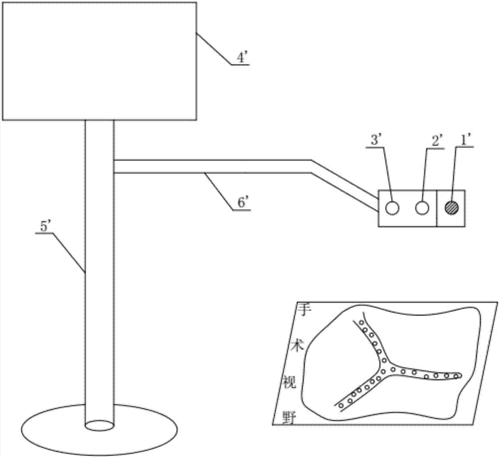
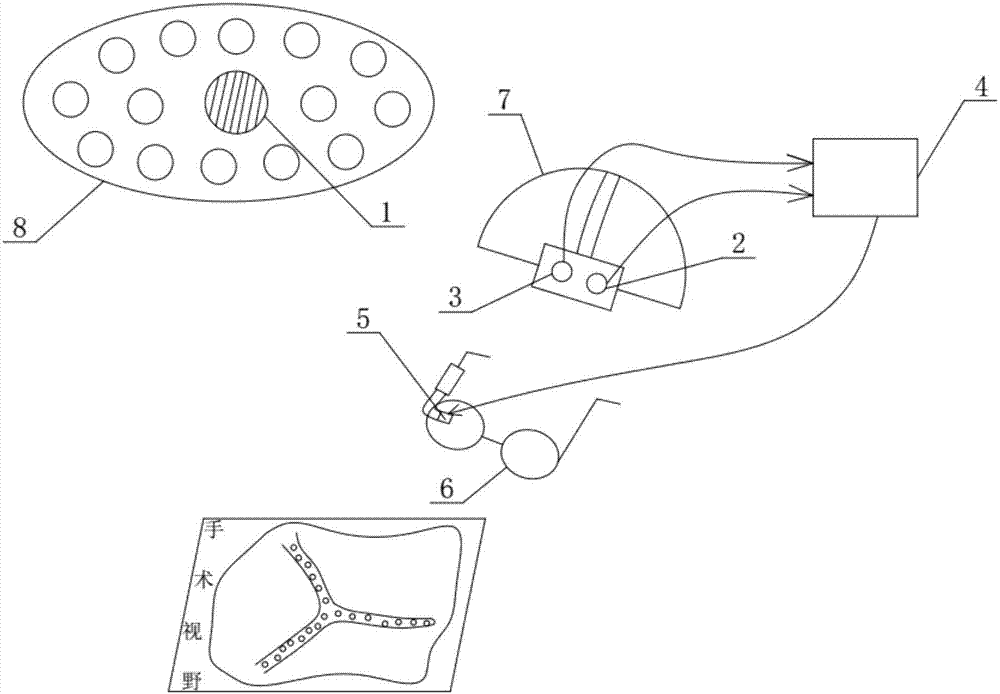
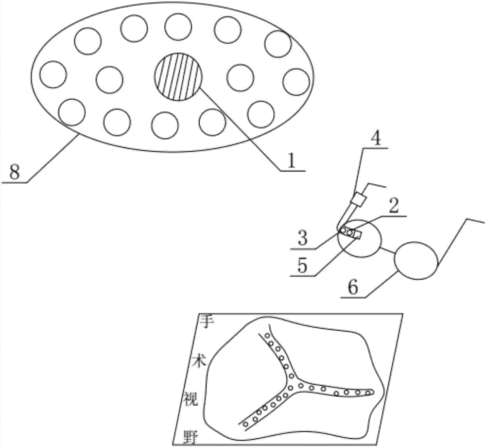
[0029] This embodiment provides an optical surgical navigation system, such as figure 2 As shown, the optical surgical navigation system includes a fluorescent excitation light source 1 , a visible light image acquisition device 2 , a near-infrared image acquisition device 3 , an image processing device 4 , a display screen 5 and other components.

[0030] In this embodiment, the fluorescence excitation light source 1 can emit invisible near-infrared light. The fluorescence excitation light source 1 can select a near-infrared light source with a reasonable wavelength band according to the fluorescent substance smeared on the tissue in the surgical field of view. The fluorescence excitation light source 1 can be installed on the goggles 6 or the head-mounted bracket 7 that can shield the near-infrared light emitted by the fluorescence excitation light source 1 directly or by using optical fibers.

[0031] The visible light image acquisition device 2 is used to acquire visible...


PUM

PropertyMeasurementUnit
Wavelengthaaaaaaaaaa

Abstract

The invention discloses an optical navigation system for surgeries, and relates to the field of medical equipment. The optical navigation system for the surgeries works in an visible light environment and comprises a fluorescence excitation light source, a visible light image collecting device, a near-infrared image collecting device, an image processing device and a display screen, the fluorescence excitation light source is capable of emitting invisible near-infrared light, the visible light image collecting device is capable of collecting visible light images formed after light emitted by a surgery illuminating device is reflected by a subject in a detect area, and the near-infrared image collecting device is capable of collecting near-infrared fluorescent images formed after light emitted by the fluorescence excitation light source is motivated by the subject in the detection area, wherein the wave length of the near-infrared fluorescent images is larger than 850 nm; the display screen is installed on a pair of goggles or a head-mounted support and used for displaying images processed by the image processing device. According to the device, fluorescence imaging is achieved in the visible light environment, the fluorescent images with high resolution and deep tissue are obtained, and imaging is clear, so that a doctor can learn about the real-time fluorescence imaging situations at any time without breaking surgical operation during the surgeries.

Description

technical field [0001] The invention belongs to the field of medical equipment, and relates to an optical surgical navigation system used in surgical operations to realize auxiliary imaging. Background technique [0002] Surgeons need to rely on visual judgment of physiological and pathological tissue structures during surgery. Existing optical aids help doctors make more accurate judgments with the help of fluorescence. [0003] Such as figure 1 As shown, an existing surgical auxiliary imaging device based on a floor stand 5' uses a near-infrared optical camera 3' (EMCCD) to image near-infrared fluorescence at a wavelength of about 800nm, and the camera is connected with a visible light camera 2' and a fluorescence excitation light source 1' are jointly fixed on the mechanical arm 6' which can be flexibly adjusted in position, and the mechanical arm 6' is installed on the floor support 5', and the generated images are displayed on the display screen 4' connected to the flo...

Claims


Application Information

Patent Timeline
IPC IPC(8): A61B34/20
CPCA61B34/20A61B90/37A61B2034/2055A61B2034/2065A61B2090/373
Inventor 刘弘光索永宽程震
Owner NORTHEASTERN UNIV
Why Eureka
Try Eureka