Microfluidic syringe filter head and use method thereof

A syringe and microfluidic technology, which is applied in the field of syringe filter heads, achieves the effects of reducing volume, facilitating miniaturization and low production cost

Active Publication Date: 2017-11-24
SOUTHEAST UNIV
View PDF3 Cites 9 Cited by
  • Summary
  • Abstract
  • Description
  • Claims
  • Application Information

AI Technical Summary

Problems solved by technology

But there is still no micron particle / cell enrichment product using microfluidic technology

Method used


Image

  • Microfluidic syringe filter head and use method thereof
  • Microfluidic syringe filter head and use method thereof
  • Microfluidic syringe filter head and use method thereof

Examples


Embodiment Construction

[0024] The implementation modes of the present invention will be described in further detail below in conjunction with the accompanying drawings.

[0025] The microfluidic syringe filter head of the present invention is a miniaturized filter head that can be directly connected to a syringe. The filter head adopts microfluidic technology to realize rapid concentration of micron particles and biological cells.

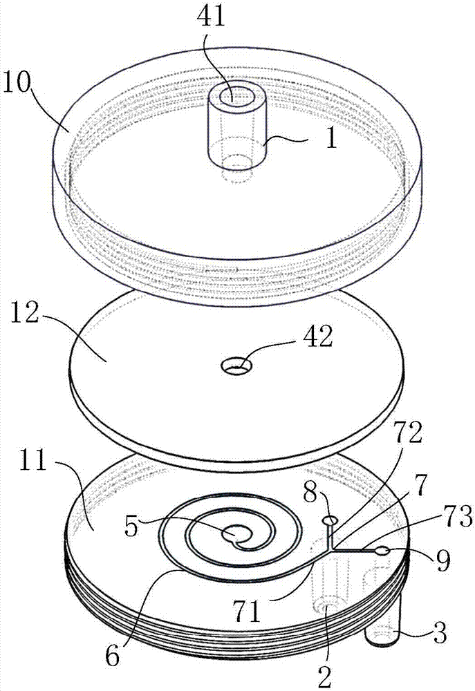
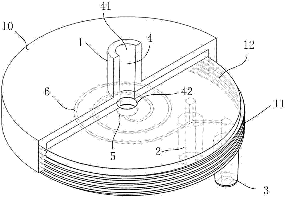
[0026] like figure 1 As shown, a microfluidic syringe filter head, its body structure includes an upper cover 10, a concentration component 11 and a sealing gasket 12, the upper cover 10 is tightly connected with the concentration component 11, and the sealing gasket 12 is arranged between the upper cover 10 and the concentration component 11 between. Among them, the upper cover 10 and the concentration component 11 can be made of materials such as medical plastics and stainless steel through injection molding, machining, three-dimensional additives and other processing...


PUM


Abstract

The invention discloses a microfluidic syringe filter head and a use method thereof. The filter head uses a microfluidic technology to concentrate and enrich micro-particles or cells, wherein a spirally extending micro-flow channel and a Y-shaped forked flow channel communicated with the micro-flow channel are formed inside the filter head; micro-particles of sample liquid are subjected to dragging force in a flowing direction, and are also subjected to inertial lifting force and Dean dragging force perpendicular to a main flowing direction in the micro-flow channel; under coupling action of the two transverse forces, the micro-particles may be gradually focused to a wall surface on one side close to a spiral center to form a regular arrangement bundle and flow out along a branch inside the Y-shaped forked flow channel so as to collect the concentrated sample liquid. The micro-flow channel and the Y-shaped forked flow channel in the invention are arranged on the same plane so as to effectively reduce a volume occupied by the flow channels and benefit to miniaturization of the filter head; the filter head is simple in use method and suitable for use in the field and low-hardware configuration laboratory environments.

Description

technical field [0001] The invention relates to a syringe filter head, in particular to a microfluidic syringe filter head for rapid concentration of micron particles and biological cells and a use method thereof. Background technique [0002] The concentration and enrichment of tangible solid components such as micron particles in liquid samples is the most frequently performed sample pretreatment step in modern biochemical and medical laboratories. For example, the labeling of cells requires the use of concentration operations to achieve the separation of redundant labeling reagents and complete the separation of labeled cell samples; the lysis of large background red blood cells in blood requires concentration to separate unlysed white blood cells from red blood cell fragments; the rapid 1. Effective diagnosis and treatment requires rapid concentration and enrichment of target pathogens from large-volume environmental source sample fluids or physiological fluids to diagno...

Claims


Application Information

Patent Timeline
Patent Type & Authority Applications(China)
IPC IPC(8): B01L3/00
CPCB01L3/5027B01L3/56
Inventor 项楠倪中华
Owner SOUTHEAST UNIV
Why Eureka
Try Eureka