
Flat-cup non-slip bolt bar knurling and thread rolling device

A bolt and anti-slip technology, which is applied in the field of screw processing, can solve the problems of low processing precision, occupying storage space, easy rolling and skewing, etc., to achieve high-precision processing, improve processing efficiency, and avoid the effect of knurling skew

Pending Publication Date: 2017-11-24
MORGAN HARDWARE KUSN
View PDF0 Cites 4 Cited by
  • Summary
  • Abstract
  • Description
  • Claims
  • Application Information

AI Technical Summary

Problems solved by technology

[0002] When the flat cup bolts are rubbed and knurled, the flat cup bolts are transported to the tooth rubbing plate through the conveyor belt. Because the flat cup bolts have a taper, if the machine is not adjusted properly, the rubbing teeth will be crooked, and the knurling of the rod will also be crooked. It is easy to be rolled and skewed, and the knurling of the rod part and the forming of the tooth part must be completed in two processes, which is time-consuming, laborious, low in efficiency, low in processing accuracy, prone to scrapped products, and intermediate products need to be stored, which takes up storage space

Method used


Image

  • Flat-cup non-slip bolt bar knurling and thread rolling device

Examples


Embodiment

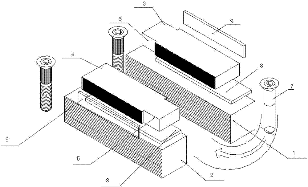
[0014] Embodiment: A kind of knurling and thread rolling device of flat cup anti-slip bolt shank, comprising movable die rubbing board 1, fixed die rubbing board 2, moving die knurling board 3 and fixed die knurling board 4, the moving die Die rubbing plate 1 and fixed die rubbing plate 2 are set facing each other, movable die knurling plate 3 and fixed die rubbing plate 4 are set oppositely, and moving die knurling plate 3 is fixedly positioned on the front of movable die rubbing plate 1. Above, the fixed die knurling plate 4 is fixedly positioned directly above the fixed die rubbing plate 2, and the opposite side walls of the movable die rubbing plate 1 and the fixed die rubbing plate 2 are respectively formed with rubbing patterns, and the moving die knurling plate 3 and the opposite side walls of the fixed die knurling plate 4 are respectively formed with knurling patterns, and the movable die rubbing plate 1 and the movable die knurling plate 3 can be opposite to the fixed...


PUM


Abstract

The invention discloses a flat-cup non-slip bolt bar knurling and thread rolling device. The flat-cup non-slip bolt bar knurling and thread rolling device is characterized in that a moving-die knurling plate is oppositely arranged with a fixed-die knurling plate, the moving-die knurling plate is fixed right above a moving-die thread rolling plate, the fixed-die knurling plate is fixed right above a fixed-die thread rolling plate, thread rolling lines are respectively formed in opposite side walls of the moving-die thread rolling plate and the fixed-die thread rolling plate, knurling lines are respectively formed in opposite side walls of the moving-die knurling plate and the fixed-die knurling plate, the moving-die thread rolling plate and the moving-die knurling plate can reciprocatingly slide dies along the extension direction of the thread rolling lines and relative to the fixed-die thread rolling plate and the fixed-die knurling plate, a first avoidance notch with a set length is formed in the side wall of one side of the fixed-die knurling plate and facing to the moving-die knurling plate and is located in one end of the bolt feeding direction, and a second avoidance notch with a set length is formed in the side wall of one side of the moving-die knurling plate and facing to the fixed-die knurling plate and is located in one end of the bolt discharging direction. By the arrangement, knurling and thread rolling of a flat cup bolt can be completed simultaneously, and the flat-cup non-slip bolt bar knurling and thread rolling device is high in machining efficiency, low in machining cost and high in precision of knurling and thread rolling.

Description

technical field [0001] The invention relates to the technical field of screw processing, in particular to a knurling and thread rolling device for the shank of a flat-cup anti-slip bolt. Background technique [0002] When the flat cup bolts are rubbed and knurled, the flat cup bolts are transported to the tooth rubbing plate through the conveyor belt. Because the flat cup bolts have a taper, if the machine is not adjusted properly, the rubbing teeth will be crooked, and the knurling of the rod will also be crooked. It is easy to be rolled and skewed, and the knurling of the rod part and the forming of the tooth part must be completed in two processes, which is time-consuming, labor-intensive, low in efficiency, low in machining accuracy, prone to scrapped products, and requires storage of intermediate products, which takes up storage space. Contents of the invention [0003] In order to overcome the above-mentioned defects, the present invention provides a knurling and thr...

Claims


Application Information

Patent Timeline
Patent Type & Authority Applications(China)
IPC IPC(8): B23G1/02B23G9/00
CPCB23G1/02B23G9/00
Inventor 凃春旺林茂森
Owner MORGAN HARDWARE KUSN
Learn More