Polishing clamp device for metallographic structure analysis and working method of polishing clamp device

A polishing fixture and metallographic structure technology, which is applied in metal processing equipment, grinding/polishing equipment, surface polishing machine tools, etc., can solve the problems of time-consuming, low production efficiency, and high design cost, so as to improve economic benefits and improve The effect of improving work efficiency and polishing quality

Pending Publication Date: 2017-11-24
WENZHOU UNIVERSITY
View PDF7 Cites 5 Cited by
  • Summary
  • Abstract
  • Description
  • Claims
  • Application Information

AI Technical Summary

Problems solved by technology

[0004] Although material researchers have invented a mechanical clamping metallographic polishing device, it is necessary to manually hold the metallographic polishing device for polishing during the polishing process, so the metallographic polishing fixture device only plays the role of fastening the sample and does not It cannot play the role of independent clamping. To complete the metallographic preparation, it is necessary to manually hold the metallographic polishing device with the sample.
Such a metallographic polishing clamping device needs to occupy the worker's time, and also makes the worker unable to leave to do other things during the polishing process, and because the polishing time is usually relatively long under normal circumstances, the person holding the polishing clamp is in a fatigued state , affecting the work e

Method used


Image

  • Polishing clamp device for metallographic structure analysis and working method of polishing clamp device
  • Polishing clamp device for metallographic structure analysis and working method of polishing clamp device
  • Polishing clamp device for metallographic structure analysis and working method of polishing clamp device

Examples


Embodiment Construction

[0042] The present invention will be further introduced below in conjunction with the accompanying drawings and specific embodiments.

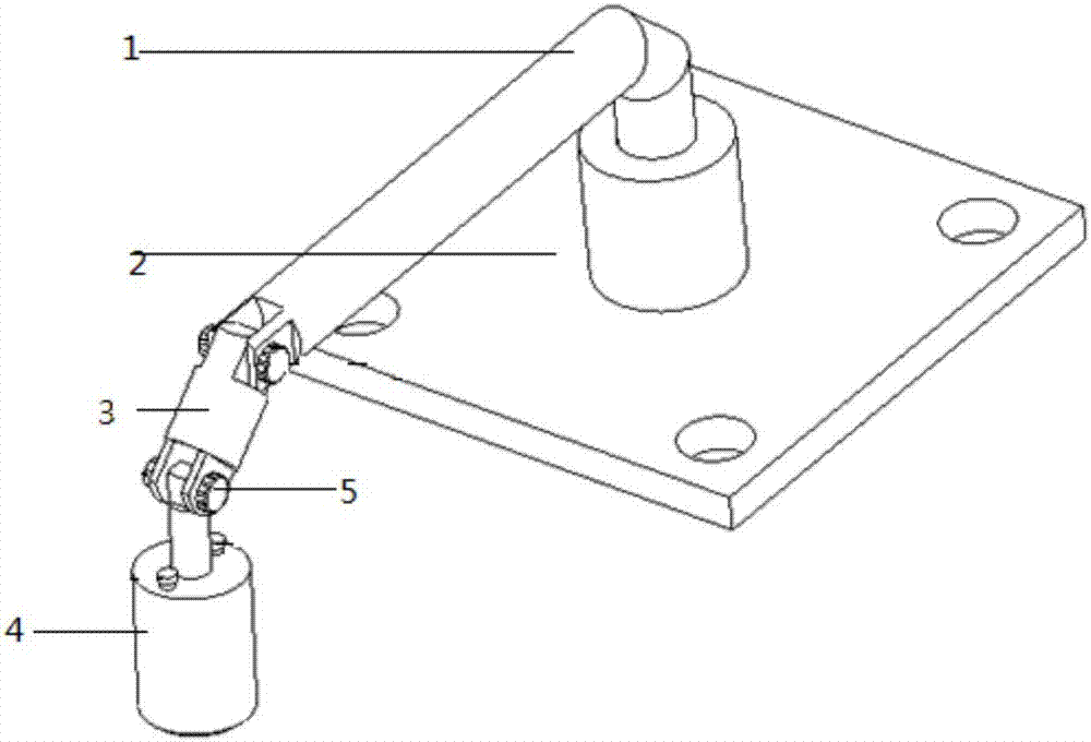
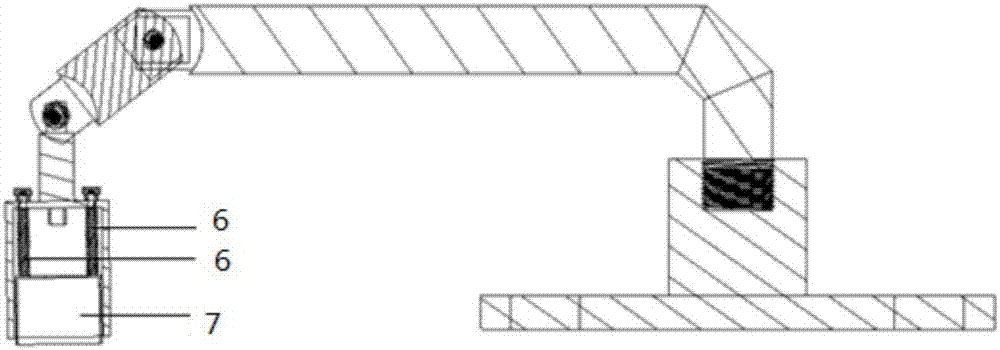
[0043] The invention discloses a metallographic sample polishing fixture device, such as figure 1 and figure 2 As shown, it consists of a base 2 installed on the polishing machine, a beam rod 1, a connecting rod 3, a sleeve shell 4 and a sleeve 7 installed inside the sleeve shell 4;

[0044] The base 2 is in the shape of a cube, and a cylinder is arranged in the middle of its upper surface, and a threaded hole is arranged in the cylinder, and the threaded hole cooperates with the external thread of the beam rod 1 for connecting the beam rod 1 .

[0045] like Figure 4 As shown, the four corners of the base 2 are respectively provided with four through holes of the same size, and the four through holes are used for fastening the base 2 and the polishing machine. The through holes distributed on the four corners of the base 2 are aligned wit...


PUM


Abstract

The invention provides a polishing clamp device for metallographic structure analysis and a working method of the polishing clamp device. The polishing clamp device comprises a base, a first connection piece, a second connection piece, a test sample clamping device and an outer shell, wherein the shell is arranged on the outer portion of the test sample clamping device. The base is fixed to a box body of a polishing machine, the first connection piece is fixedly connected with the base, one end of the second connection piece is movably connected with a first connection piece, the other end of the second connection piece is movably connected with the outer shell, and the test sample clamping device is arranged in the outer shell and connected with the outer shell. The device has the advantages that the polishing clamp device is adopted to replace manual operation, so that the work efficiency is greatly improved; positive pressure is stably and elastically provided through springs, so that the polishing test sample is stressed uniformly, the polished surface is balanced, and the polishing quality is improved; the problem about the design of a polishing clamp on the polishing machine is solved, and the polishing clamp device is convenient to disassemble and flexible to adjust.

Description

technical field [0001] The invention relates to the technical field of metallographic sample preparation, in particular to a metallographic structure analysis polishing jig device arranged on a polishing machine and a working method thereof. Background technique [0002] Metallographic sample preparation technology is an important link in the observation of the microstructure of metal materials. It is a basic skill for material researchers to prepare qualified metallographic samples quickly, conveniently and efficiently. At present, when materials researchers prepare metallographic samples, the researchers can still polish the samples by hand when the samples are large. If the samples are relatively small, it will take time and effort for the researchers to polish by hand and the polishing effect is not ideal. [0003] Usually, for small samples, metallographic samples are often prepared by mosaic method, which mainly inlays small samples on the lower surface of a regular cy...

Claims


Application Information

Patent Timeline
IPC IPC(8): B24B29/02B24B41/06B24B49/16G01N1/32
CPCG01N1/32B24B29/02B24B41/06B24B49/16
Inventor 孙树峰章斌王萍萍孙术彬庄梅孙萌
Owner WENZHOU UNIVERSITY
Why Eureka
Try Eureka