Grinding and polishing clamp for oval workpiece

A technology for polishing fixtures and workpieces, applied in the direction of grinding workpiece supports, etc., can solve the problems of unfavorable mass production, large labor, and low production efficiency.

Active Publication Date: 2017-11-24
GUANGDONG LXD ROBOTICS CO LTD
View PDF6 Cites 4 Cited by
  • Summary
  • Abstract
  • Description
  • Claims
  • Application Information

AI Technical Summary

Problems solved by technology

[0002] The existing grinding methods for products are generally processed by manual grinding, but because the product wall thickness is relatively thin, generally only 0.5mm, and the surface temperature of the product is high due to mutual friction during grinding, which makes the product easy to deform. And the surface temperature of the product is easy to burn workers. It can be seen that the traditional processing had the following problems at that time: 1. Due to the need for manual processing and polishing, it resulted in a large amount of labor, and it was difficult to guarantee the processing quality. Moreover, the production efficiency was low, which was not conducive to batch production. Production; 2. Manual processing and polishing requires the human body to be in contact with the product. As the surface temperature of the product rises, it is easy to cause burns to workers. If the processing process is frequently cooled, the production efficiency will be lowered; 3. The force of manual processing and grinding is difficult. Guarantee, during the grinding process, the product wall thickness is thinner and the temperature rises, resulting in easy softening of the product, and manual force can easily cause product deformation and affect product quality
The structure is complicated, and the operation is troublesome. The clamping effect on the elliptical workpiece is average, and the reliability is low. Moreover, the tool clamps the outer surface of the elliptical workpiece, so it cannot be used for grinding and polishing the outer surface.

Method used


Image

  • Grinding and polishing clamp for oval workpiece
  • Grinding and polishing clamp for oval workpiece
  • Grinding and polishing clamp for oval workpiece

Examples


Embodiment Construction

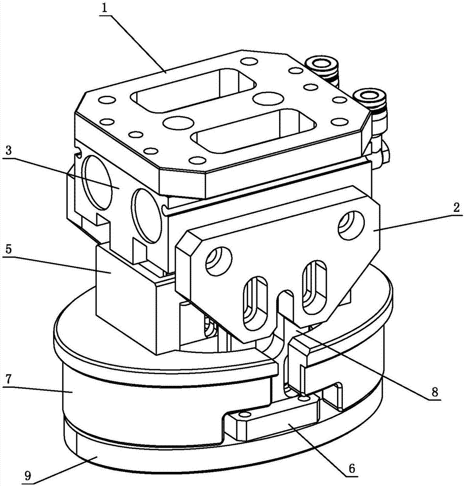
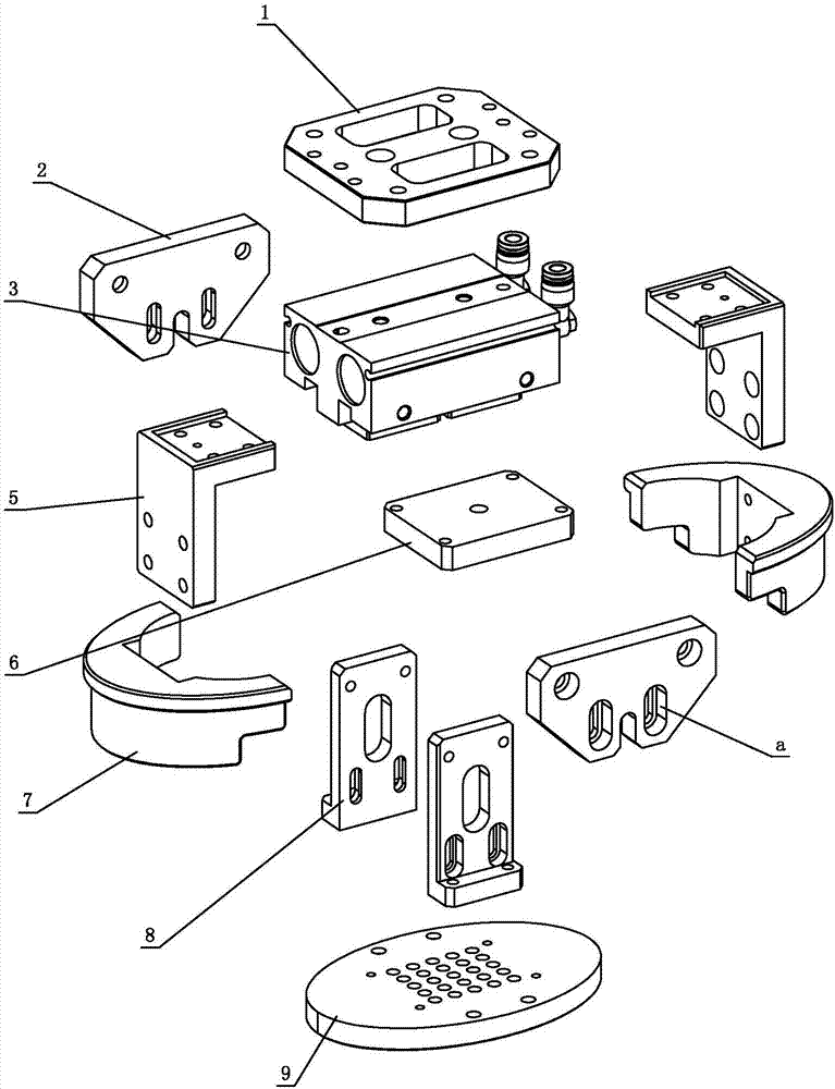
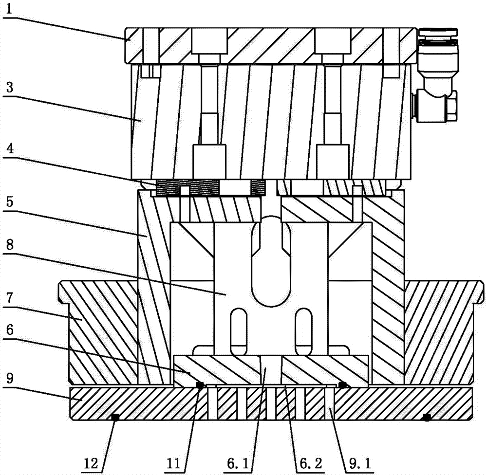
[0022] The present invention will be further described below in conjunction with the accompanying drawings and embodiments.

[0023] see Figure 1-Figure 8 , the grinding and polishing fixture used for the ellipse workpiece includes a clamping power assembly, a suction cup positioning block 9 and two mutually symmetrical clamping finger blocks 7; the suction cup positioning block 9 is adjustable relative to the clamping power assembly, and the suction cup positioning block 9 The middle part is processed with a number of air intake through holes 9.1 connected to the vacuum pumping device; the two clamping finger blocks 7 are set to reciprocate and slide relative to the clamping power assembly, and under the action of clamping the power assembly, the two symmetrical clamping finger blocks 7 move closer to each other or move away from each other; the two clamp finger blocks 7 are arranged above the suction cup positioning block 9 . When working, the two clamping finger blocks 7 ...


PUM


Abstract

The invention relates to a grinding and polishing clamp for an oval workpiece. The clamp comprises a clamping power assembly, an adhesive disc positioning block, and an even number of clamping blocks, wherein every two of the clamping blocks are symmetric; the adhesive disc positioning block is adjustably arranged relative to the clamping power assembly, and a plurality of air inlet through holes which are communicated with a vacuum pumping device are formed in the adhesive disc positioning block; all the clamping blocks are back and forth arranged relative to the clamping power assembly in a sliding mode respectively, and under the effect of the clamping power assembly, two symmetric clamping blocks move close to each other or more away from each other; all the clamping blocks are arranged above the adhesive disc positioning block. According to the grinding and polishing clamp, the clamping blocks clamp the oval workpiece, and the deformation and scratch of the oval workpiece can be avoided; in addition, the adhesive disc positioning block is effectively attached to the bottom of an inner cavity of the oval workpiece, so that the clamping effect is more stable, and the problem that products deform after being grinded and polished can be solved.

Description

technical field [0001] The invention relates to a grinding and polishing jig, in particular to a grinding and polishing jig for an ellipse workpiece. Background technique [0002] The existing grinding methods for products are generally processed by manual grinding, but because the product wall thickness is relatively thin, generally only 0.5mm, and the surface temperature of the product is relatively high due to mutual friction during grinding, which in turn causes the product to be easily deformed. And the surface temperature of the product is easy to burn workers. It can be seen that the traditional processing had the following problems at that time: 1. Due to the need for manual processing and polishing, it resulted in a large amount of labor, and it was difficult to guarantee the processing quality. Moreover, the production efficiency was low, which was not conducive to batch production. Production; 2. Manual processing and polishing requires the human body to be in con...

Claims


Application Information

Patent Timeline
Patent Type & Authority Applications(China)
IPC IPC(8): B24B41/06
CPCB24B41/06Y02P70/10
Inventor 周贝贝曾磊周全
Owner GUANGDONG LXD ROBOTICS CO LTD
Why Eureka
Try Eureka