Self-walking gantry lifting device

A lifting device and self-propelled technology, which is applied in the direction of hoisting equipment braking device, hoisting device, transportation and packaging, etc., can solve problems such as lifting work that is not suitable for cylindrical equipment, and achieve saving loading and unloading time, low site requirements, The effect of multiple application scenarios

Inactive Publication Date: 2017-11-24
JIANGHAN UNIVERSITY
View PDF13 Cites 8 Cited by
  • Summary
  • Abstract
  • Description
  • Claims
  • Application Information

AI Technical Summary

Problems solved by technology

For example, the invention patent CN103626040A discloses a two-stage lift-type lifting frame with adjustable lifting width. A two-stage lifter is provided through a modular design for adjusting the height of the legs, but its disadvantage is that this design is only for some special scenes, and it is not suitable for lifting work of larger cylindrical equipment

Method used


Image

  • Self-walking gantry lifting device
  • Self-walking gantry lifting device
  • Self-walking gantry lifting device

Examples


Embodiment Construction

[0025] The present invention will be further described below in conjunction with specific examples.

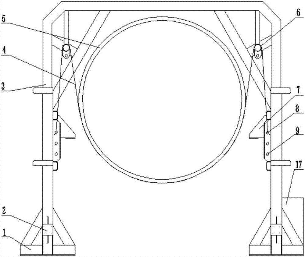
[0026] figure 1 The structure of the present invention is shown. A self-propelled gantry lifting device comprises a main girder, supporting feet, a lifting mechanism, a self-propelling mechanism and an adjustable hoisting mechanism. A support 7 is arranged on the inner side of the foot along the direction of the main beam.

[0027] 1. Lifting mechanism

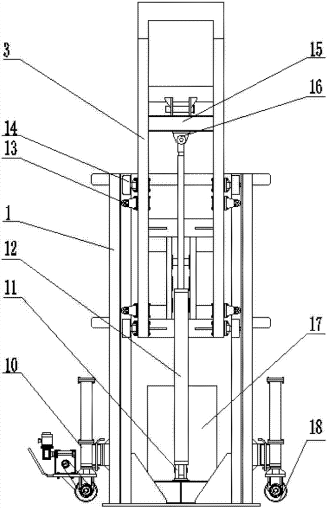
[0028] figure 2 The structure of the crane 3 is shown. The support foot includes a frame base 1 and a column, and a lifting mechanism is arranged on the column. The lifting mechanism includes a lifting frame 3 and a jacking hydraulic telescopic cylinder 12. The lifting frame 3 is nested into the column of the supporting foot in a "U" shape. And form a gantry structure with it, the beam of lifting frame 3 is the main beam. The upper ends of both sides of the lifting frame 3 are sequentially provided with a fixed seat 16 ...


PUM


Abstract

The invention discloses a self-walking gantry lifting device. The self-walking gantry lifting device comprises supporting feet and is characterized in that lifting mechanisms are arranged on the supporting feet and comprise lifting frames and jacking hydraulic telescoping cylinders, the lifting frames are nested into the supporting feet in a U-shaped mode and form a gantry structure with the supporting feet; each supporting foot comprises a frame-type base and a column, self-walking mechanisms are arranged at the lower ends of the columns and comprise driving wheels, driven wheels and diesel generators; adjustable hoisting mechanisms are arranged on the lifting frames and comprise positioning pin hole plates, fixed pulleys and hoisting belts. The self-walking gantry lifting device has the advantages that the design of the adjustable hoisting mechanisms is adopted, so that the device is suitable for hoisting of cylindrical devices and can be used for transporting different diameters of workpieces; the design of the supporting foot structures is adopted, so that the loading-unloading time is saved, and an application range is wide; the design of the self-walking mechanisms is adopted, the device has low the field requirements, has no track installation requirement and is suitable for lots of application scenarios.

Description

technical field [0001] The invention relates to the technical field of hoisting equipment, in particular to a gantry lifting device. Background technique [0002] Large cylindrical equipment is often used in petroleum, chemical, metallurgy, wind power and other industries, such as various cylindrical containers, reactors, boilers and wind power towers, etc. In order to meet the strict manufacturing inspection requirements, such equipment is generally transported to the yard for storage after the manufacturing enterprise completes the processing or directly to the user's site for installation. However, the processing and transshipment of finished products have become a major technical bottleneck restricting the manufacture of large cylindrical equipment. [0003] Due to the complex structure and high cost of the load-bearing beam of conventional gantry cranes, and the high requirements of gantry cranes on the foundation, special tracks need to be laid, which takes a long tim...

Claims


Application Information

Patent Timeline
Patent Type & Authority Applications(China)
IPC IPC(8): B66C5/02B66C1/18B66C13/00
CPCB66C1/18B66C5/02B66C13/00
Inventor 李敏徐美成荣佑民赵梦婷
Owner JIANGHAN UNIVERSITY
Why Eureka
Try Eureka