An optical fiber preform dehydration process and an optical fiber
An optical fiber preform and process technology, which is applied in the field of optical fiber, can solve the problems of high barrier layer density, inability to clean loose core layer, insufficient dehydration atmosphere, etc., and achieve the effect of water peak reduction
- Summary
- Abstract
- Description
- Claims
- Application Information
AI Technical Summary
Problems solved by technology
Method used
Image


Examples
Embodiment 1
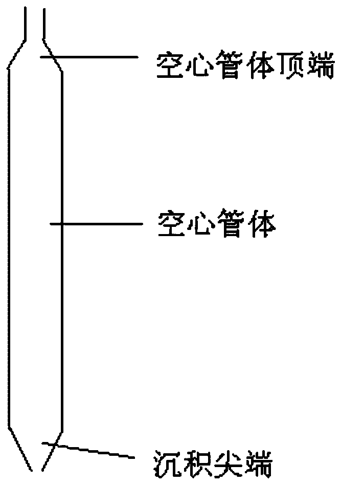
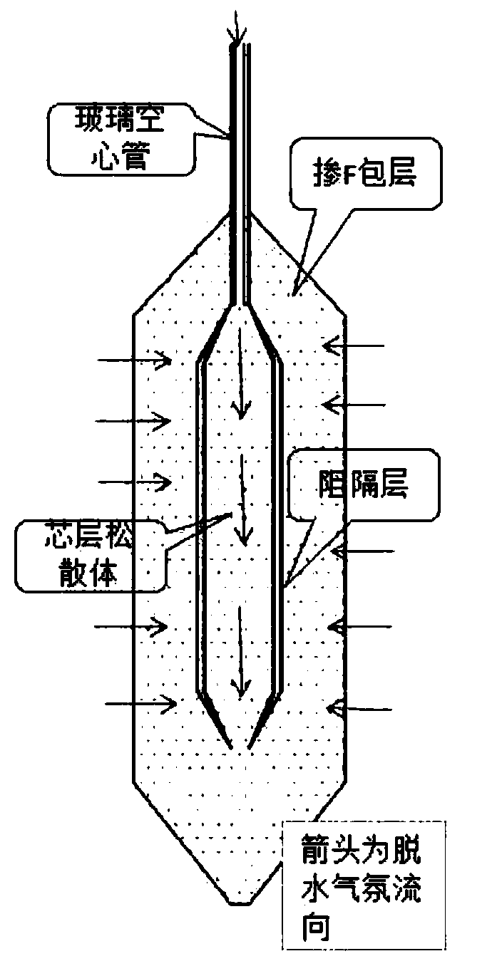
[0048] The hollow glass tube is used as the target rod, and the core rod loose body, which is the core layer loose body, the silica barrier layer and the cladding loose body, is prepared from the inside to the outside by the VAD method, such as figure 2 As shown, the hollow glass tube includes a hollow tube body and an open deposition tip communicated with the end of the hollow tube body, the open deposition tip is conical, and the length of the deposition tip is 20mm. The deposition tip is provided with a hole with a diameter of 6 mm, the inner diameter of the hollow body of the hollow glass tube is 30 mm, and the outer diameter of the hollow body of the hollow glass tube is 32 mm.
[0049] The first blowtorch, the second blowtorch and the third blowtorch arranged in sequence from bottom to top are arranged in the cavity of the device for preparing loose mandrel by VAD method.
[0050] Wherein, the gas passed into the first torch is H 2 , O 2 , Ar and SiCl 4 , the first t...
Embodiment 2
[0067] The hollow glass tube is used as the target rod, and the core rod loose body, which is the core layer loose body, the silica barrier layer and the cladding loose body, is prepared from the inside to the outside by the VAD method, such as figure 2 As shown, the hollow glass tube includes a hollow tube body and an open deposition tip communicated with the end of the hollow tube body, the open deposition tip is conical, and the length of the deposition tip is 20 mm. The deposition tip is provided with a hole with a diameter of 6 mm, the inner diameter of the hollow body of the hollow glass tube is 30 mm, and the outer diameter of the hollow body of the hollow glass tube is 32 mm.
[0068] The first blowtorch, the second blowtorch and the third blowtorch arranged in sequence from bottom to top are arranged in the cavity of the device for preparing loose mandrel by VAD method.
[0069] Wherein, the gas passed into the first torch is H 2 , O 2 , Ar and SiCl 4 , the first ...
Embodiment 3
[0081] The hollow glass tube is used as the target rod, and the core rod loose body, which is the core layer loose body, the silica barrier layer and the cladding loose body, is prepared from the inside to the outside by the VAD method, such as figure 2 As shown, the hollow glass tube includes a hollow tube body and an open deposition tip communicated with the end of the hollow tube body, the open deposition tip is conical, and the length of the deposition tip is 20 mm. The deposition tip is provided with a hole with a diameter of 6 mm, the inner diameter of the hollow body of the hollow glass tube is 30 mm, and the outer diameter of the hollow body of the hollow glass tube is 32 mm.
[0082] The first blowtorch, the second blowtorch and the third blowtorch arranged in sequence from bottom to top are arranged in the cavity of the device for preparing loose mandrel by VAD method.
[0083] Wherein, the gas passed into the first torch is H 2 , O 2 , Ar and SiCl 4 , the first ...
PUM
| Property | Measurement | Unit |
|---|---|---|
| length | aaaaa | aaaaa |
| diameter | aaaaa | aaaaa |
| length | aaaaa | aaaaa |
Abstract
Description
Claims
Application Information
 - R&D
- Intellectual Property
- Life Sciences
- Materials
- Tech Scout
- Unparalleled Data Quality
- Higher Quality Content
- 60% Fewer Hallucinations
Browse by: Latest US Patents, China's latest patents, Technical Efficacy Thesaurus, Application Domain, Technology Topic, Popular Technical Reports.
© 2025 PatSnap. All rights reserved.Legal|Privacy policy|Modern Slavery Act Transparency Statement|Sitemap|About US| Contact US: help@patsnap.com