Lifter screw rod rotation-stopping structure

A lift and anti-rotation technology, applied in the field of lifts, to save processing and assembly procedures, reduce wall thickness, and save materials

Active Publication Date: 2017-11-24
BEIJING XINLI MACHINERY
View PDF7 Cites 1 Cited by
  • Summary
  • Abstract
  • Description
  • Claims
  • Application Information

AI Technical Summary

Problems solved by technology

Also for installing screws, the end cover 4 is affected by the screws on the axial length, and the end cover 4 is also limited in the radial wall thickness

Method used


Image

  • Lifter screw rod rotation-stopping structure
  • Lifter screw rod rotation-stopping structure

Examples


Embodiment Construction

[0017] The present invention will be further described below in conjunction with the accompanying drawings and specific embodiments. Examples of said embodiments are shown in the accompanying drawings, and the embodiments described with reference to the accompanying drawings are only exemplary and are only used for explaining the invention and not for limiting the invention.

[0018] The directions and positional relationships indicated by the terms "front", "rear", "left", and "right" described in the present invention are based on the directions and positional relationships shown in the drawings, and are only for convenience and simplification of description, not indicative Nor should it be construed as limiting the invention if it implies a particular orientation that the device or element referred to must have.

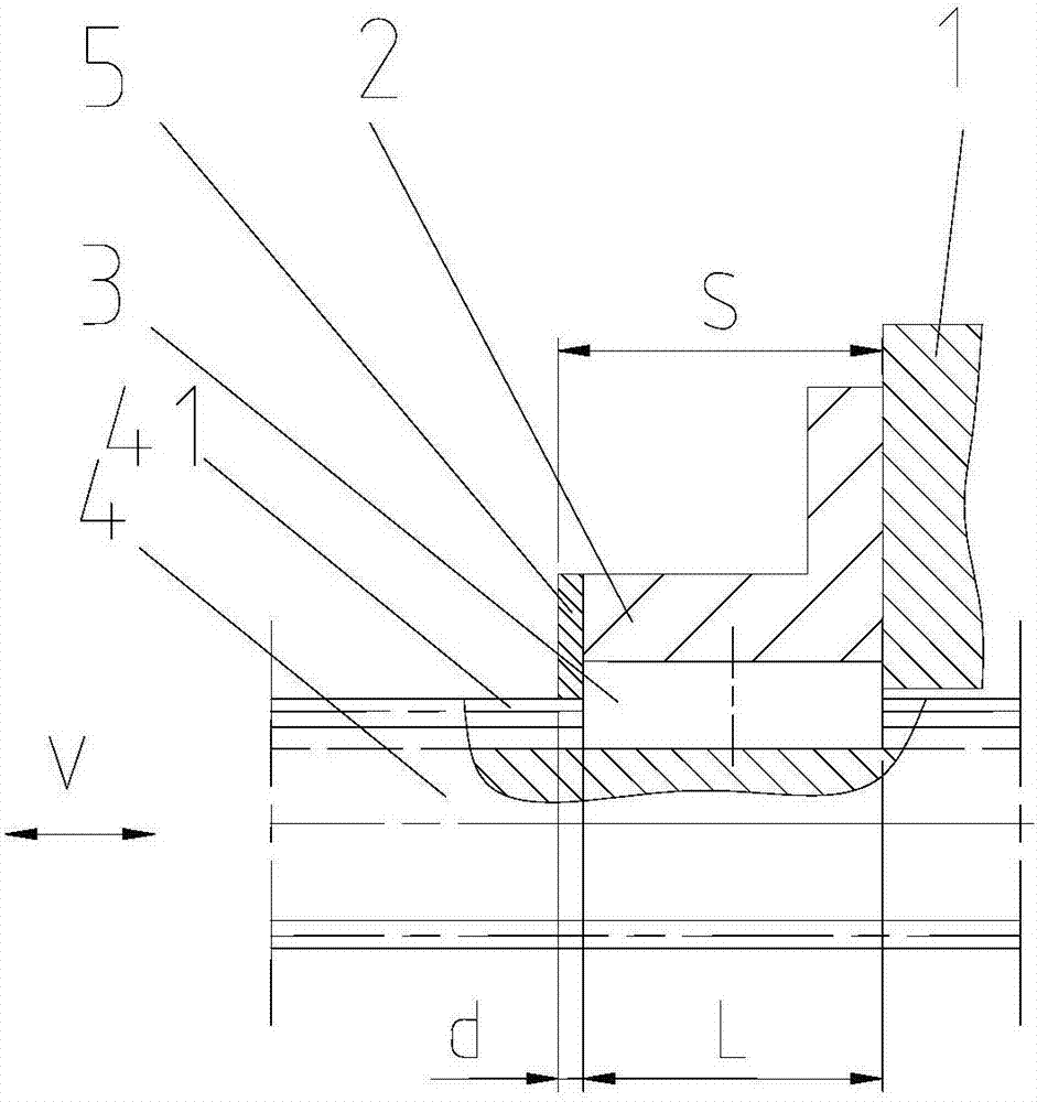
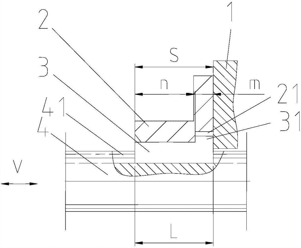
[0019] Such as figure 2 As shown, the anti-rotation structure of the screw rod of the elevator includes an end cover 2 and a sliding key 3, the end cover 2 is f...


PUM


Abstract

The invention discloses a lifter screw rod rotation-stopping structure, which comprises an end cover and a sliding key. The end cover is fixedly connected onto a machine base; a screw rod is provided with a sliding chute; the end cover is provided with the sliding key; the lower end of the sliding key is in sliding fit to the sliding chute; the upper end of the sliding key is embedded into the end cover so as to stop rotation; a sliding key shoulder part is arranged at the upper side of the right end of the sliding key; a groove matched with the sliding key shoulder part and used for inserting the sliding key shoulder part is formed in a position, corresponding to the sliding key shoulder part, on the end cover; the left end face of the sliding key shoulder part presses against the groove, and the right end face of the sliding key shoulder part presses against the machine base, so that the sliding key is positioned in a screw rod movement direction; and the upper end face of the sliding key presses against the end cover, and the lower end face of the sliding key presses against the sliding chute, so that the sliding key is positioned in a radial direction.

Description

technical field [0001] The invention relates to the technical field of elevators, in particular to an anti-rotation structure of an elevator screw rod. Background technique [0002] The elevator drives the screw to rise or fall by driving the nut to rotate, which is a method to realize lifting. In order to ensure the lifting function in this method, the lead screw must be prohibited from rotating. The general method is to install a feather key that can prevent the lead screw from rotating and allow the lead screw to move. The feather key must be fixed to effectively prevent the screw from rotating. [0003] Existing lift feather key fixing structure, see figure 1 . figure 1 Among them, the end cover plug 5 and the end cover 2 frame 1 are strung together on the lead screw 4 from left to right. The lead screw 4 is provided with a chute 41, the end cover 2 is equipped with a sliding key 3, and the lower end of the sliding key 3 is connected to the sliding The groove 41 is s...

Claims


Application Information

Patent Timeline
Patent Type & Authority Applications(China)
IPC IPC(8): F16H25/24B66F13/00
Inventor 郭苑军黄莉莉尹孝
Owner BEIJING XINLI MACHINERY
Why Eureka
Try Eureka