
High-temperature charging bucket movable combined sealing pressing device

A combined sealing and pressing device technology, applied in the direction of engine sealing, pressure vessel, engine components, etc., can solve problems such as jamming, high-temperature corrosion of sealing rings, and affecting the service life of components, so as to reduce the probability of overflow and prevent high temperature Corrosion, the effect of avoiding direct contact

Pending Publication Date: 2017-11-24
SHENWU TECH GRP CO LTD
View PDF0 Cites 6 Cited by
  • Summary
  • Abstract
  • Description
  • Claims
  • Application Information

AI Technical Summary

Problems solved by technology

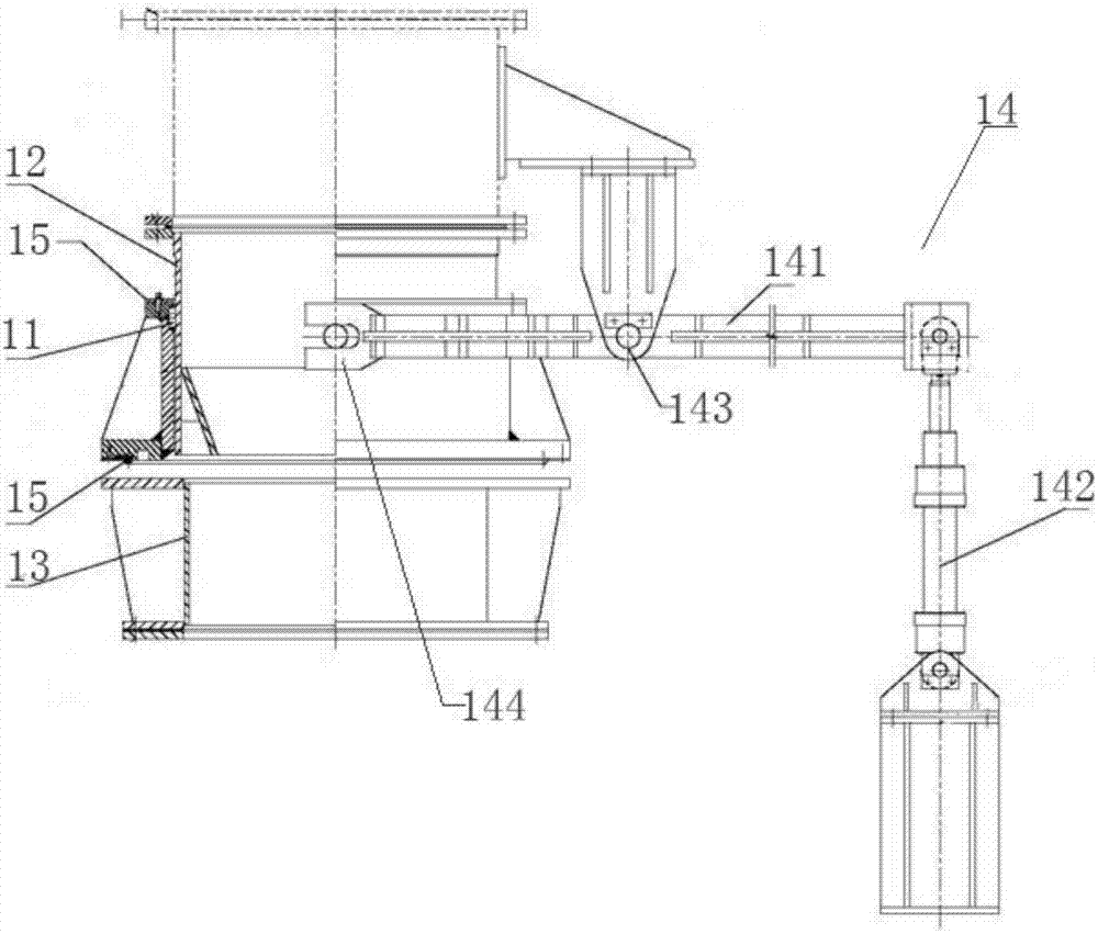
However, the above-mentioned sealing device still has some defects: 1) when the temperature of the material is too high, it will cause the volume expansion of the upper and lower feeding cylinder 12, which will affect the up and down movement of the liftable sealing cover 11, and the whole equipment will be easily damaged when the lifting device 14 is started to move forcibly; 2) The lifting device 14 utilizes the principle of leverage to move the U-shaped opening 144 located at the other end of the connecting rod 141 to move up and down by activating the hydraulic cylinder 142 located at one end of the connecting rod 141 with the pin shaft 143 as a fulcrum, so that the liftable sealing cover can be moved up and down easily. Lateral deviation occurs during the up and down movement, which causes it to fail to move concentrically with the upper and lower barrels, resulting in jamming and poor sealing, causing material leakage; 3) When the temperature of the material is too high, high-temperature gas overflows the seal Components such as ring 15 cause high temperature corrosion, which seriously affects the service life of these components

Method used


Image

  • High-temperature charging bucket movable combined sealing pressing device
  • High-temperature charging bucket movable combined sealing pressing device
  • High-temperature charging bucket movable combined sealing pressing device

Examples


Embodiment Construction

[0029] Embodiments of the present invention are described in detail below, examples of which are shown in the drawings, wherein the same or similar reference numerals designate the same or similar elements or elements having the same or similar functions throughout. The embodiments described below by referring to the figures are exemplary only for explaining the present invention and should not be construed as limiting the present invention.

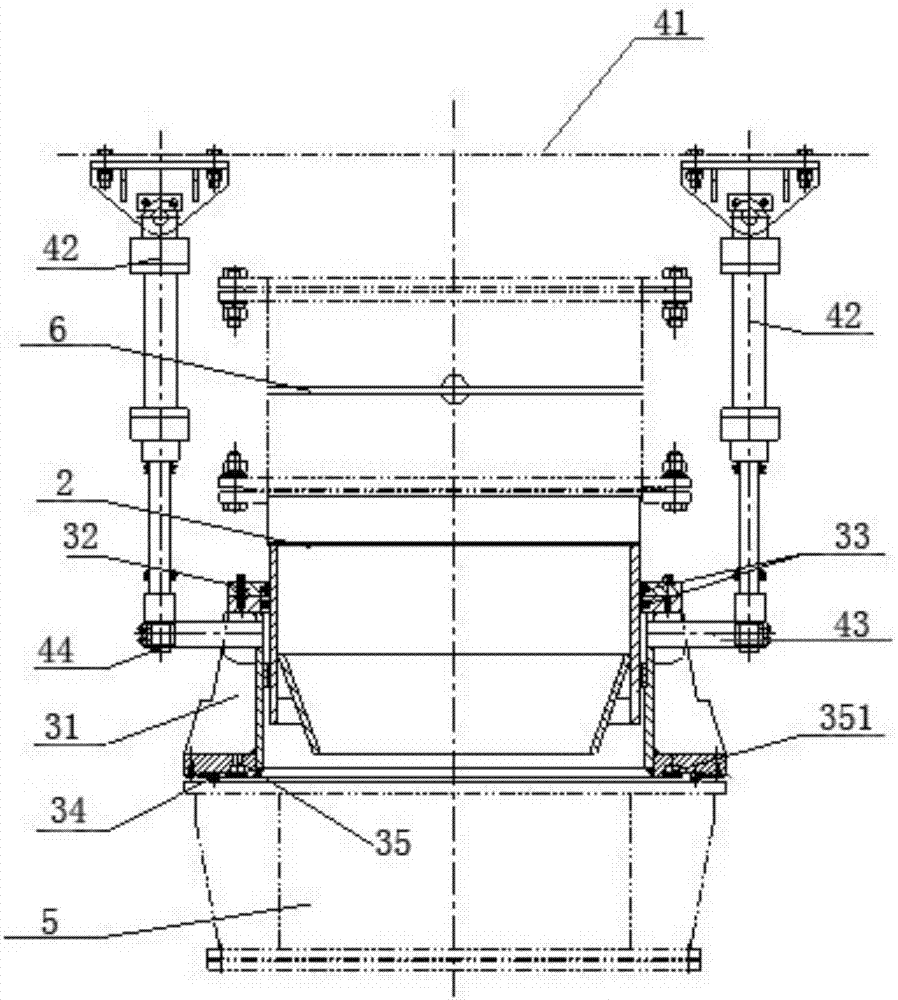
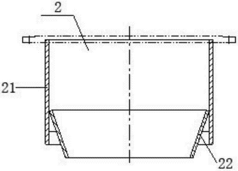
[0030] attached figure 2 A movable combined sealing and pressing device for a high-temperature material tank is shown, which includes a feeding cylinder 2, a sealing mechanism and a driving mechanism. The sealing mechanism mainly includes a cylindrical liftable sealing cover 31 concentrically sleeved on the outside of the feeding cylinder 2 . The liftable sealing cover 31 can move up and down relative to the feeding cylinder 2 driven by the driving mechanism. Wherein, the upper end of the liftable sealing cover 31 is sealingly connect...


PUM


Abstract

The invention discloses a movable combined sealing and pressing device for a high-temperature material tank, which comprises a feeding cylinder, a sealing mechanism and a driving mechanism. The upper end of the upper end is sealed and connected with the feeding barrel, and the lower end is sealed and connected with the storage tank during the unloading process. There is a thermal expansion gap between the inner wall of the lifting sealing cover and the outer wall of the feeding barrel; the driving mechanism drives the lifting sealing cover relative to The feeding cylinder moves up and down. The device uses thermal expansion gap design to solve the problem of hindering the upward and downward movement of the liftable sealing cover due to thermal expansion, and ensures good concentricity of the equipment through the structural design of the driving mechanism, making the unloading process easy to operate and safer.

Description

technical field [0001] The invention relates to the technical field of material conveying, in particular to a movable combined sealing and compacting device for a high-temperature material tank with good sealing performance and high reliability. Background technique [0002] In the process of material transportation, the leakage of materials such as hot air or dust may easily cause environmental pollution and waste of resources. When the leaked materials contain toxic substances, it will seriously deteriorate the working environment and endanger the health of the staff. At present, the more commonly used sealing measures are the use of liftable sealing covers, such as figure 1 As shown, the liftable sealing cover 11 is sleeved on the outside of the upper blanking cylinder 12 and can move up and down along the upper blanking cylinder 12 through the lifting device. , until it is airtightly connected with the drop barrel 13. This equipment can not only realize the dynamic con...

Claims


Application Information

Patent Timeline
IPC IPC(8): F16J15/10F16J13/00
CPCF16J15/104F16J13/00
Inventor 吴钰锋余幼民王东方吴道洪
Owner SHENWU TECH GRP CO LTD
Learn More