Inlet manifold sensor structure

A technology for intake manifolds and sensors, which is applied to instruments, measuring devices, etc., can solve problems such as low utilization of installation space and complex processes, and achieve the effects of reducing process costs, firm connections, and reduced processes

Pending Publication Date: 2017-11-24
ZHEJIANG WODELL TECH
View PDF25 Cites 0 Cited by
  • Summary
  • Abstract
  • Description
  • Claims
  • Application Information

AI Technical Summary

Problems solved by technology

[0004] At the same time, the present invention also provides an intake manifold sensor structure that can directly connect the connecting wire of the temperature sensitive element to the circuit board, has simple process and rational utilization of installation space; solves the problem of temperature sensitivity in the prior art The connecting lines of the components need to open up the installation space separately, the utilization rate of the installation space is low, and the technical problems of the complicated process

Method used


Image

  • Inlet manifold sensor structure
  • Inlet manifold sensor structure
  • Inlet manifold sensor structure

Examples


Embodiment

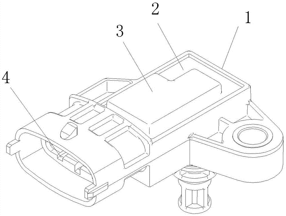
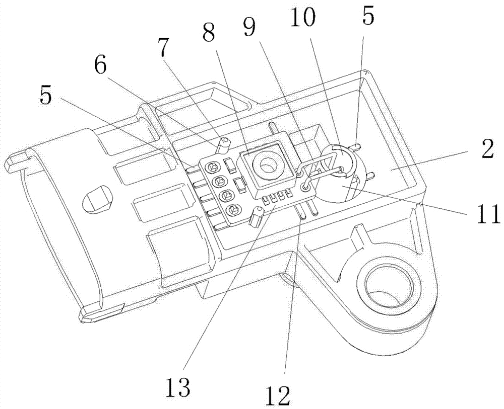
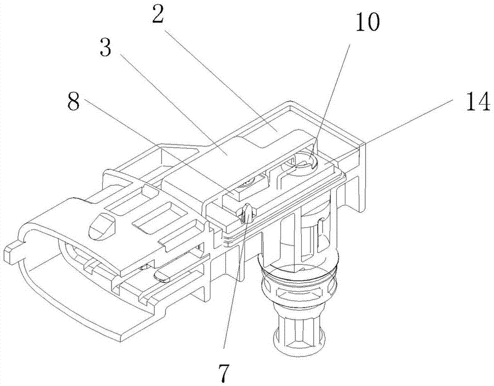
[0023] Such as figure 1 and 2 As shown in and 3 and 4, an intake manifold sensor structure includes a housing 1, and a mounting surface 2 is provided on one side of the housing 1, and the mounting surface 2 is recessed downward to form an open type that can accommodate glue filling. space. An airflow guide pipe 11 is connected below the installation surface 2 . One end of the airflow guide pipe 11 protrudes above the installation surface 2, and the pressure airflow is pressed in from the bottom of the airflow guide pipe 11, and flows out from the air outlet 10 of the airflow guide pipe 11 above the installation surface. A temperature sensitive element 18 is installed in the lower half of the airflow guiding pipe 11 , and the connecting wire 9 of the temperature sensitive element 18 is led out from the airflow guiding pipe 11 .

[0024] A circuit board 13 is installed outside the airflow outlet 10 of the airflow guide tube, and the circuit board 13 is connected to an externa...


PUM


Abstract

The invention relates to a mounting structure of a sensor. The inlet manifold sensor structure includes a housing, wherein a mounting surface is arranged in the housing; an air-flow guide tube is connected with the lower part of the mounting surface; a pressure sensing element is arranged on the mounting surface; the pressure sensing element is arranged at one side of an air-flow outlet of the air-flow guide tube; the sensing port of the pressure sensing element faces upward; a cover plate is arranged over the pressure sensing element and the air-flow outlet; by means of one time of glues pouring, the cover plate is fixed on the mounting surface; and an enclosed mounting cavity is formed between the cover plate and the mounting surface. The inlet manifold sensor structure is simple in packaging process, only needs one time of dispensing, thus reducing the assembling process and improving the production efficiency, and can effectively satisfy the pressure range and accuracy index for application of customers. The inlet manifold sensor structure solves the technical problem that the prior art is complicated in packaging process, having more assembling steps, needing more technological devices, needing multiple times of dispensing, and being long in the production cycle.

Description

technical field [0001] The invention relates to a sensor installation structure, in particular to a sensor structure installed on an intake manifold. Background technique [0002] The intake manifold is a major part of the automobile engine. Pressure sensitive elements and temperature sensitive elements need to be installed on the intake manifold to test the pressure and temperature of the airflow entering the intake manifold. At present, the overall packaging of pressure sensitive components on automobile engines is usually packaged in a metal shell. The disadvantages are high cost of metal, long processing process (machining, electroplating treatment), easy damage to the appearance, and corrosion resistance. Poor sex. The sealing of the conventional pressure sensitive element is through the compression of the sealing ring between the pressure ring and the housing, and the compression of the sealing ring between the terminal button and the housing to seal the sensor. The ...

Claims


Application Information

Patent Timeline
Patent Type & Authority Applications(China)
IPC IPC(8): G01D21/02
CPCG01D21/02
Inventor 康元福刘建强曾茂根陈雁
Owner ZHEJIANG WODELL TECH
Why Eureka
Try Eureka