Battery core stacking clamp

A battery cell and fixture technology, which is applied in the direction of circuits, electrical components, secondary batteries, etc., can solve the problems of inconvenient cell stacking equipment processing, increase the difficulty of production debugging, and increase the production cycle, so as to avoid hard contact and extend equipment The effect of long service life and simple structure

Pending Publication Date: 2017-11-24
SUZHOU JEE INTELLIGENT EQUIP CO LTD
0 Cites 1 Cited by

AI-Extracted Technical Summary

Problems solved by technology

[0003] The cell stacking process is an indispensable production link in the production process of new energy batteries. During the stacking process, it is necessary to ensure that the poles of different cells are in a straight line. The existing cell stacking equipment is designed separately, and its structure is simple, often The placement slot placed horizontally, because the placement slot is horizontal, during the stacking process, there is a risk of the cell falling over due to the movement of the manipulator or the vibration of the stacking equipment.
[0004] Therefore, in order to avoid this risk, some cell stacking equipme...

Method used

Simultaneously, described pedestal, first support column, second support column, the 3rd support column are all positioned on a base plate, and described base plate 9 is arranged on the fixture conveying line (not shown in the figure), described The fixture conveying line can be a variety of conveying structures, such as linear guide rails or sliding structures of guide rails plus sliders and cylinders, etc., which will not be repeated here, so that the cell stacking fixture of this patent can be integrated in the cell blanking station and other processing stations without the need for the structure of a 6-axis robot that handles the batteries on the stacking device; and preferably there are two clamp conveying lines, and each clamp c...

Abstract

The invention discloses a battery core stacking clamp, which comprises a support plate. The support plate is provided with at least one placement platform for stacking battery cores and a floating pressing device for applying pressure to a group of battery cores and making the battery cores prop against a limiting block of each placement platform; the support plate is parallel to the horizontal plane in a first state; the support plate and the horizontal plane keep an acute angle in a second state; and each limiting block in the second state is lower than that in the first state. The battery core stacking clamp is ingenious in design; the support plate can be switched between the horizontal state and the inclined state, so that the inclined state can be kept when the battery cores are stacked, and the battery cores are prevented from dumping; the battery cores are switched into the horizontal state after stacking is completed and thus can be directly transported to the next station for processing, integration with equipment in other procedures is facilitated, and the problem of a single function of stacking equipment is solved; and meanwhile, the condition that the battery cores do not dump when switched into the horizontal state from the inclined state can be ensured in combination with the floating pressing device.

Application Domain

Technology Topic

Image

  • Battery core stacking clamp
  • Battery core stacking clamp
  • Battery core stacking clamp

Examples

  • Experimental program(1)

Example Embodiment

[0030] The purpose, advantages and characteristics of the present invention will be illustrated and explained through the following non-limiting description of preferred embodiments. These embodiments are only typical examples of applying the technical solutions of the present invention, and any technical solutions formed by equivalent substitutions or equivalent transformations fall within the protection scope of the present invention.
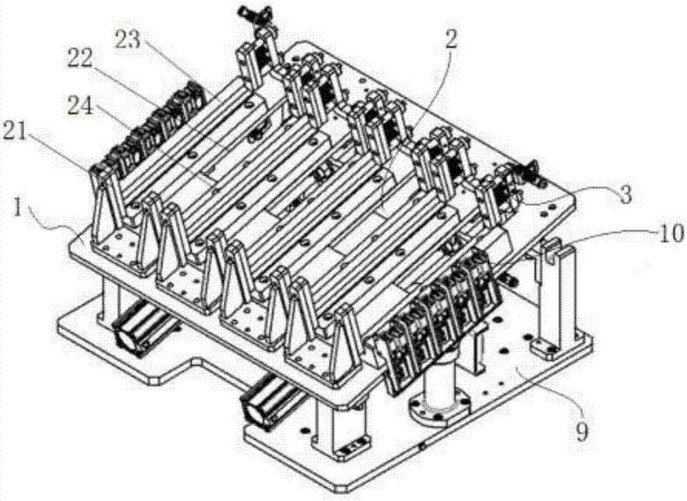
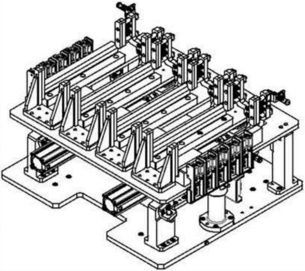
[0031] The invention discloses a cell stacking fixture, as attached figure 1 As shown, it includes a support plate 1 on which at least one placement platform 2 for stack discharge cores and a limit block 21 for applying pressure to a group of cells and making them abut against the placement platform are provided. Floating pressing device 3 on the top, as attached figure 1 , Attached figure 2 As shown,
[0032] In the first state, the support plate 1 is parallel to the horizontal plane;
[0033] In the second state, the support plate 1 maintains an acute angle with the horizontal plane;
[0034] The position of the limiting block 21 in the second state is lower than its position in the first state.
[0035] Wherein, the support plate 1 can be a flat plate of any shape and size. In this embodiment, it is preferably a rectangular shape. There are four placement platforms 2 arranged side by side. Each placement platform 2 is formed with a position limiter. The limit slot 22 of the battery, and the four limit slots 22 are formed by mirror-symmetrical L-shaped support blocks 23 on both sides and three convex support blocks 24 in the middle position. One end of the limit slot 22 is provided with a As for the limit block 21, the floating pressing device 3 is arranged at the other end of the limit slot 22, and the limit slot 22, the limit block 21 and the area in contact with the battery are made of insulating materials.
[0036] Specifically, as attached image 3 As shown, the floating pressing device 3 includes a driving cylinder 31 located at the bottom of the support plate 1. The telescopic shaft of the driving cylinder 31 is connected to a connecting bracket 33 located above the support plate 1 through a connecting piece 32. The connecting member 32 is Y-shaped and slidably arranged on the guide rail 37 below the support plate 1, and each branch is provided with a connecting bracket, so that two connecting brackets 33 can be driven by a driving cylinder to work simultaneously, which simplifies Equipment structure.
[0037] The corresponding support plate 1 is provided with a through hole for the connecting member 32 to penetrate and move, and each two branches are respectively connected to a connecting bracket 33, the connecting bracket 33 is also a Y-shaped structure, so Each branch of the connecting bracket 33 is provided with a set of guide posts 34 perpendicular to it. Preferably, there are two guide posts 34, and the free ends of the guide posts 34 can be in the through holes provided on the pressing plate 35 Telescopic, the end surface of the pressing plate 35 in contact with the battery is made of insulating material, and a set of springs 36, preferably two, are arranged between the pressing plate 35 and the connecting bracket 33, and one end of the two springs 36 is fixed to the The other end of the pressing plate 35 is fixed on the connecting bracket 33.
[0038] Moreover, it is preferable in this embodiment that the floating pressing device 3 corresponding to the four limiting grooves 22 is driven by two driving cylinders 31, and the floating pressure corresponding to the two limiting grooves 22 on the same side of the symmetry axis in the longitudinal direction of the support plate 1 The tightening device 3 is driven by the same driving cylinder 31.
[0039] At the same time, in order to determine how many batteries are placed on each limit slot 22, as attached figure 1 As shown, a set of workpiece sensors 10 are respectively provided on both sides of the support plate 1 and the placing platform 2 perpendicular to each other. Preferably, a set of 10 workpiece sensors 10 are arranged side by side, and one workpiece sensor is used to determine a workpiece.
[0040] Further, in order to enable the support plate 1 to be turned over, as attached Figure 4 As shown, the bottom of the support plate 1 is pivotally connected to a set of first support columns 4 on the same straight line through a flip hinge 8. In this embodiment, there are preferably two first support columns 4, and they are connected to each other. The two sides of the supporting plate 1 in the longitudinal direction are close to each other, and the top end of each first supporting column 4 is formed with a mounting groove, and the turning hinge is rotatably arranged in the mounting groove through a rotating shaft, so that the supporting The board 1 can be turned over.
[0041] In addition, a set of second support columns 5 and a set of third support columns 6 are provided on both sides of a set of the first support columns 4,
[0042] As attached figure 2 As shown, in the first state, the support plate 1 is supported by a set of first support columns 4 and a set of second support columns 5;
[0043] As attached figure 1 As shown, in the second state, the support plate 1 is supported by a set of first support columns 4 and a set of third support columns 6.
[0044] In detail, as attached Figure 4 As shown, there are preferably two second support columns 5, and the line connecting the center points of the two second support columns 5 is parallel to the line connecting the center points of the first support columns 4, and each The second support column 5 is provided with a positioning groove 51, and the bottom surface of the support plate 1 is provided with a positioning block 11 matching each positioning groove 51. When the support plate 1 is in the first state, the positioning block 11 They are respectively embedded in a positioning slot 51, so as to realize the limitation of the support plate 1 in the left and right direction; at the same time, each of the second support columns 5 is provided with a leveling nut 52 and a first buffer perpendicular to the support plate. 53. Adjust the protruding height of the leveling nut 52 to level the support plate 1.
[0045] There are preferably two third support columns 5, and the top surface 61 of each third support column 6 is an inclined surface, and its inclination angle is the same as the angle between the support plate and the horizontal plane in the second state. The bottom surface of the supporting surface 1 is attached to the inclined surface; and each of the third buffer columns is provided with a second buffer 62 which is perpendicular to the inclined surface, thereby effectively avoiding The supporting plate 1 hardly contacts the inclined surface when it is turned over.
[0046] Furthermore, in order to realize the overturning of the support plate 1, a certain amount of power needs to be applied to the support plate 1. Correspondingly, the bottom of the support plate 1 is also provided to drive the support plate 1 in the first state and The drive mechanism 7 for switching between the second states, the drive mechanism 7 includes a telescopic cylinder 71, the fixed end of the telescopic cylinder 71 is pivotally connected to a base, and the telescopic end is pivotally connected to the support plate 1. The bottom connector 72 is on.
[0047] At the same time, the base, the first support column, the second support column, and the third support column are all located on a substrate, and the substrate 9 is arranged on a fixture conveying line (not shown in the figure), and the fixture conveying line It can be a variety of conveying structures, such as a linear guide rail or a sliding structure with a guide rail plus a slider plus a cylinder, etc., which will not be repeated here, so that the cell stacking fixture of this patent can be integrated in the cell blanking station and other processing Between stations, the structure of the 6-axis robot that handles the cells on the stacking device is omitted; and preferably there are two clamp conveying lines, and each clamp conveying line is provided with one cell stacking clamp, thereby Can improve the efficiency of cell transmission.
[0048] When working, when stacking batteries, the telescopic shaft of the telescopic cylinder 71 extends, pushing the support plate 1 to turn into a tilted state. At this time, the support plate 1 and the inclined surface of the third support column 6 fit the limit The cell stacking mechanism places the cells one by one in the limit slot 22, and the workpiece sensor determines the position of the placed cells in real time, so as to control the next placement position of the cell stacking mechanism. When a limit slot When all the 10 workpiece sensors in 22 sense the cells, the cell stacking mechanism is controlled to place the cells in the adjacent limit slots 22. When the two limit slots 22 corresponding to the same drive cylinder 31 are both When the batteries are fully filled, the driving cylinder 31 drives the pressing plate 35 to move to compress a group of batteries; when all the batteries are stacked in the limit slots 22 and pressed by the pressing plate 35, the The telescopic shaft of the telescopic cylinder retracts, pulls the support plate 1 and turns the positioning block 11 on the support plate 1 into the positioning groove on the second support column 5, and then adjusts the leveling The nut adjusts the support plate 1 to a horizontal state.
[0049] At this point, the entire cell stacking fixture can be transported to the next station for processing through the fixture transport line.
[0050] The present invention has many implementation modes, and all technical solutions formed by equivalent transformations or equivalent transformations fall within the protection scope of the present invention.

PUM

no PUM

Description & Claims & Application Information

We can also present the details of the Description, Claims and Application information to help users get a comprehensive understanding of the technical details of the patent, such as background art, summary of invention, brief description of drawings, description of embodiments, and other original content. On the other hand, users can also determine the specific scope of protection of the technology through the list of claims; as well as understand the changes in the life cycle of the technology with the presentation of the patent timeline. Login to view more.

Similar technology patents

Pedal type tableware storage cabinet

Owner:SHENZHEN NAISHIDI TECH DEV CO LTD

Training flying disc special for pet

ActiveCN109220879AExquisite designImprove fun and responsivenessTaming and training devicesAirflowMagnet
Owner:FUNAN NATURE ARTS & CRAFTS

Inserted and connected type ball

ActiveCN103895926AExquisite designWell foldedRigid containersIsosceles trapezoidDiagonal
Owner:铜陵市创威科技有限责任公司

Classification and recommendation of technical efficacy words

  • Exquisite design
  • Simple structure

Microlithographic projection exposure apparatus

InactiveUS20050068499A1Simple structureReliable and low-maintenance operationProjectorsPhotomechanical exposure apparatusCamera lensPhysics
Owner:CARL ZEISS SMT GMBH
Why Eureka
Try Eureka