

Protective circuit
A technology for protecting circuits and voltage dividing resistors, applied in the direction of protection against overvoltage, etc., can solve problems such as damage, abnormal operation of other parts of the system, backfilling power supply, etc., and achieve the effect of ensuring normal operation
- Summary
- Abstract
- Description
- Claims
- Application Information
AI Technical Summary
Problems solved by technology
Method used
Image

Examples
Embodiment 1
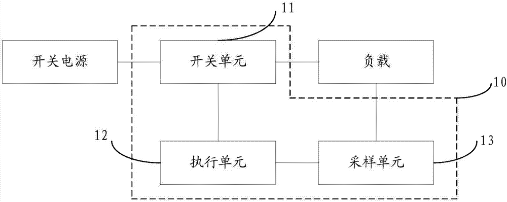
[0021] like figure 1 Shown is a schematic diagram of an application environment of a protection circuit provided by an embodiment of the present invention; figure 2 A protection circuit provided by an embodiment of the present invention.
[0022] The embodiment of the present invention provides a protection circuit 10, including: a switch unit 11, an execution unit 12, and a sampling unit 13;
[0023] The switch unit 11 is arranged between the switching power supply and the load end, including: a first controllable switch;
[0024] connected in parallel with the input end and output end of the first controllable switch or embedded in the start-up diode of the first controllable switch;
[0025] a first voltage dividing resistor connected in parallel with the control terminal and the output terminal of the first controllable switch;
[0026] A second voltage-dividing resistor connected in series with the first voltage-dividing resistor for voltage division;
[0027] The s...
Embodiment 2
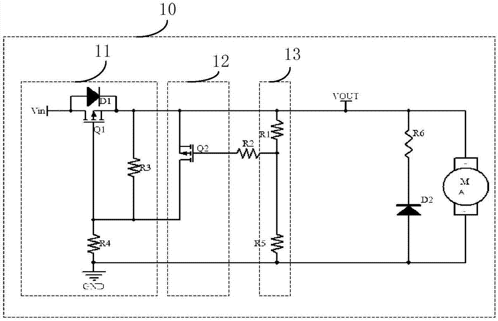
[0033] In the embodiment of the present invention, such as figure 2 Shown is a protection circuit provided by the embodiment of the present invention.
[0034] In the embodiment of the present invention, the switch unit 11 includes: a first controllable switch, a starting diode D1, a first voltage dividing resistor R3 and a second voltage dividing resistor R4; wherein, the first controllable switch is a P-channel MOS transistor Q1, the start-up diode D1 is connected in parallel with the drain and source of the MOS transistor Q1, or in another embodiment of the present invention, the start-up diode can be directly built into the MOS transistor Q1, which is the internal body of the first controllable switch Diodes, the first voltage dividing resistor R3 is connected in parallel with the source and gate of the MOS transistor Q1, and the second voltage dividing resistor R4 is connected in series with the first voltage dividing resistor R3 to divide the voltage.
[0035] The samp...
Embodiment 3
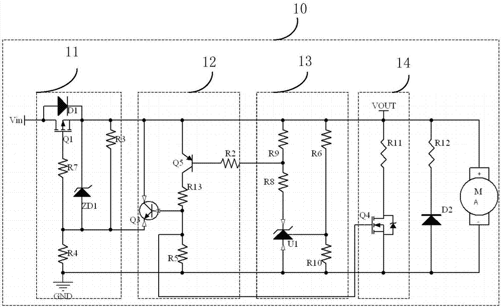
[0041] like image 3 As shown, the protection circuit provided by the embodiment of the present invention differs from the second embodiment in that:
[0042] In the embodiment of the present invention, the execution unit 12 includes: a third controllable switch Q3 and a fourth controllable switch Q5; wherein, the third controllable switch is an NPN transistor Q3, and its emitter and collector are connected in parallel to the first branch Both ends of the piezoresistor R3, the base is connected to the fourth controllable switch; the fourth controllable switch is a PNP transistor Q5, the base of which is connected to the current limiting resistor R2, the emitter is connected between the switch unit 11 and the load, and the collector It is coupled to the base of the transistor Q3. It plays the role of current amplification and improves the turn-off speed of the switch unit 11 . The sampling unit 13 includes: the fifth voltage dividing resistor R9, the sixth voltage dividing resi...
PUM
 Abstract
Description
Claims
Application Information