Photovoltaic power generation system

A technology of photovoltaic power generation and solar photovoltaic panels, applied in the direction of photovoltaic power generation, support structures of photovoltaic modules, photovoltaic modules, etc., can solve the problems of destructive processing of photovoltaic modules, low luminous efficiency of photovoltaic modules, and poor stability of support structures, etc. Photovoltaic luminous efficiency, easy mass production, and the effect of avoiding scratches

Active Publication Date: 2017-11-24
北京蓝海华业科技股份有限公司
View PDF8 Cites 5 Cited by
  • Summary
  • Abstract
  • Description
  • Claims
  • Application Information

AI Technical Summary

Problems solved by technology

[0006] In view of this, the present invention provides a photovoltaic power generation system, which solves the problems of low luminous efficiency of photovoltaic modules, poor support structure stability, destructive processing of photovoltaic modules during fixed installation, and difficult disassembly once installed in the prior art.

Method used


Image

  • Photovoltaic power generation system
  • Photovoltaic power generation system
  • Photovoltaic power generation system

Examples


Embodiment 1

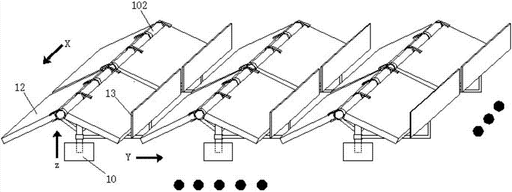
[0047] Such as Figure 1-3 As shown, the photovoltaic power generation system includes:

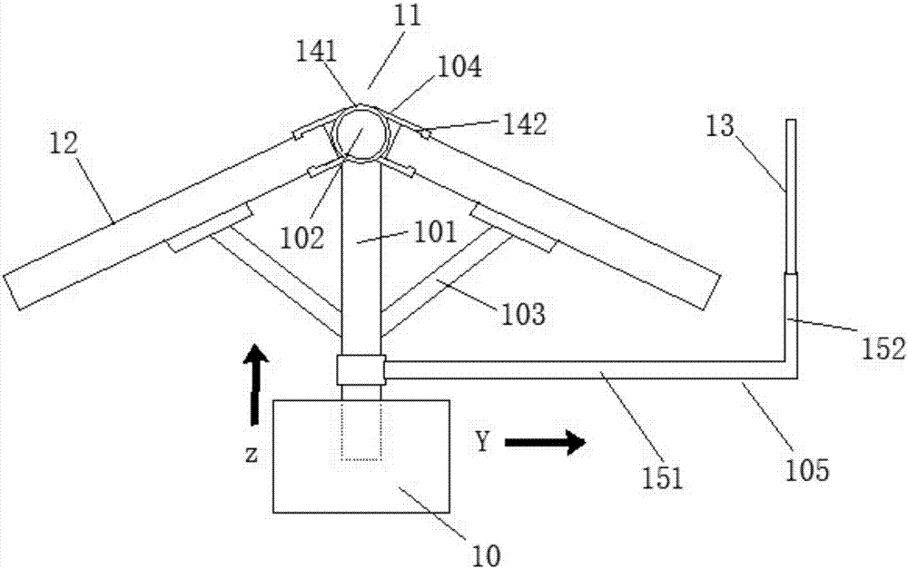
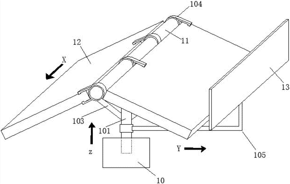
[0048] Such as figure 1 As shown, a plurality of support structures 11 arranged in an array on the fixed foundation 10, a solar photovoltaic panel 12 and a double-sided reflective element 13 fixed on the support structure 11, wherein; the support structure is installed on the fixed foundation, The arrangement of the support structure can be changed by moving the fixed foundation, avoiding drilling holes on the ground or roof for fixed installation. The fixed foundation described in this embodiment can be prepared by using reinforced concrete, so that it has sufficient firmness.

[0049] The support structure 11 includes: a support column 101 installed on the fixed foundation 10 and extending along the first direction Z, wherein the support shaft 102 is a cylindrical structure, and the support column 101 is fixed on the When the foundation 10 is fixed, the first direction Z is a vertical ...

Embodiment 2

[0062] Such as Figure 4-6 As shown, the photovoltaic power generation system includes:

[0063] Installed on the support structure 21 arranged in an array on the fixed foundation 20, the solar photovoltaic panel 22 and the double-sided reflective element 23 fixed on the said support structure 21, wherein; the support structure is installed on the fixed foundation, by moving the fixed foundation The arrangement structure of the support structure can be changed to avoid drilling holes on the ground or roof for fixed installation. The fixed foundation described in this embodiment can be prepared by using reinforced concrete, so that it has sufficient firmness.

[0064] The support structure 21 includes: a support column 201 installed on the fixed foundation 20 and extending along the first direction Z, wherein the support shaft 202 is a cylindrical structure, and the support column 201 is fixed on the When the base 20 is fixed, the first direction Z is a vertical direction.

...


PUM


Abstract

The invention discloses a photovoltaic power generation system. The system comprises supporting structures, solar photovoltaic cells and double-side reflecting elements, wherein the supporting structures are installed on a fixing basis and distributed in an arrayed mode, and the solar photovoltaic cells and the double-sided reflecting elements are fixed to the supporting structures; each supporting structure comprises a supporting column, a supporting shaft and telescopic supporting frames, wherein the supporting column is installed on the fixing basis, the supporting shaft is fixed to the end, away from the fixing basis, of the supporting column, and the telescopic supporting frames are symmetrically arranged on the supporting column with the supporting column and the supporting shaft as axes of symmetry respectively; the ends, away from the supporting column, of the two supporting frames are fixed to the bottom surface of one solar photovoltaic cell respectively; each supporting shaft is provided with at least four clamping mounting parts, wherein the clamping mounting parts comprise circular rings and buckles, and the circular rings of the clamping mounting parts are installed on the supporting shafts in a sleeving mode and distributed at intervals; L-shaped fixing supports are connected to the supporting columns for fixation of the double-side reflecting elements. By means of the photovoltaic power generation system, the problems that in the prior art, the luminous efficiency of a photovoltaic assembly is low, the stability of supporting structures is poor and disassembly is not easy once installation is conducted are solved.

Description

technical field [0001] The present invention relates to the field of new energy technologies, and more specifically, to a photovoltaic power generation system. Background technique [0002] No matter from the perspective of the world or China, conventional energy is very limited. China's primary energy reserves are far below the world's average level, only about 10% of the world's total reserves. Solar energy is an inexhaustible renewable energy for human beings. It has sufficient cleanliness, absolute safety, relative extensiveness, long life and maintenance-free, resource adequacy and potential economy. It has an important position in the long-term energy strategy. [0003] Therefore, reducing the dependence on coal-fired power generation and increasing the use of renewable energy will be the development direction of the country's future energy policy. Therefore, as an important means of energy saving and emission reduction, photovoltaic power generation is getting more ...

Claims


Application Information

Patent Timeline
Patent Type & Authority Applications(China)
IPC IPC(8): H02S20/30
CPCH02S20/30Y02E10/50
Inventor 逯金重李静许庆礼王升王先君
Owner 北京蓝海华业科技股份有限公司
Why Eureka
Try Eureka