Semi-automatic fire fighting truck

A semi-automatic, fire truck technology, applied in fire rescue and other directions, can solve problems such as cost, water loss, insufficient jet power, etc., to ensure transmission stability, easy installation and maintenance, and high use efficiency.

Active Publication Date: 2017-11-28
KAIFENG UNIV
View PDF5 Cites 1 Cited by
  • Summary
  • Abstract
  • Description
  • Claims
  • Application Information

AI Technical Summary

Problems solved by technology

In the face of modern fires, the combat performance of active fire trucks obviously cannot meet the needs, mainly in the following aspects: First, the sprayed fire extinguishing agent cannot give full play to its fire extinguishing efficiency. Lost, fire extinguishing efficiency is not high
To extinguish a large fire, it is necessary to maintain the fire extinguishing concentration of the fire extinguishing agent in the combustion zone, and it is necessary to continuously spray the fire extinguishing agent, which often causes serious water damage and chemical pollution to the environment; secondly, the injection power is insufficient, which is affected by the structural strength of the car and the matching of the engine power. The ratio of the power of the active fire engine power plant to the mass of the vehicle is difficult to break through the limit of 30kW / t
In the face of large-scale fires, the injection power of a single fire truck is insufficient, and it is impossible to inject a large amount of effective fire extinguishing agent to the fire scene in a short period of time, and it is impossible to control the fire and quickly extinguish the fire in the first place. Hundreds of fire trucks work together, costing a lot

Method used


Image

  • Semi-automatic fire fighting truck
  • Semi-automatic fire fighting truck
  • Semi-automatic fire fighting truck

Examples


Embodiment Construction

[0029] The specific implementation manners of the present invention will be described in detail below in conjunction with the accompanying drawings.

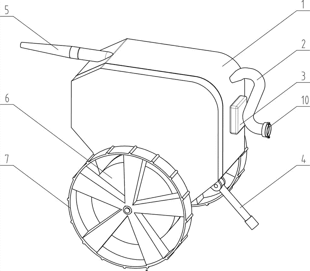
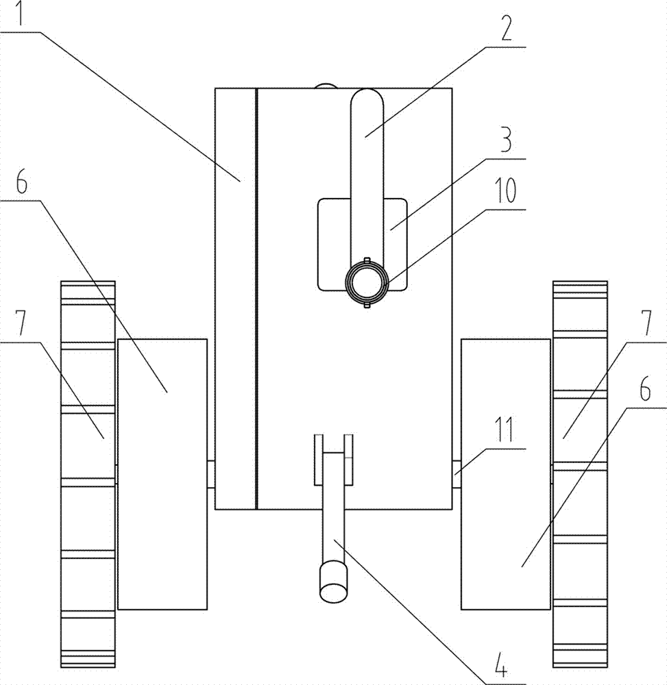
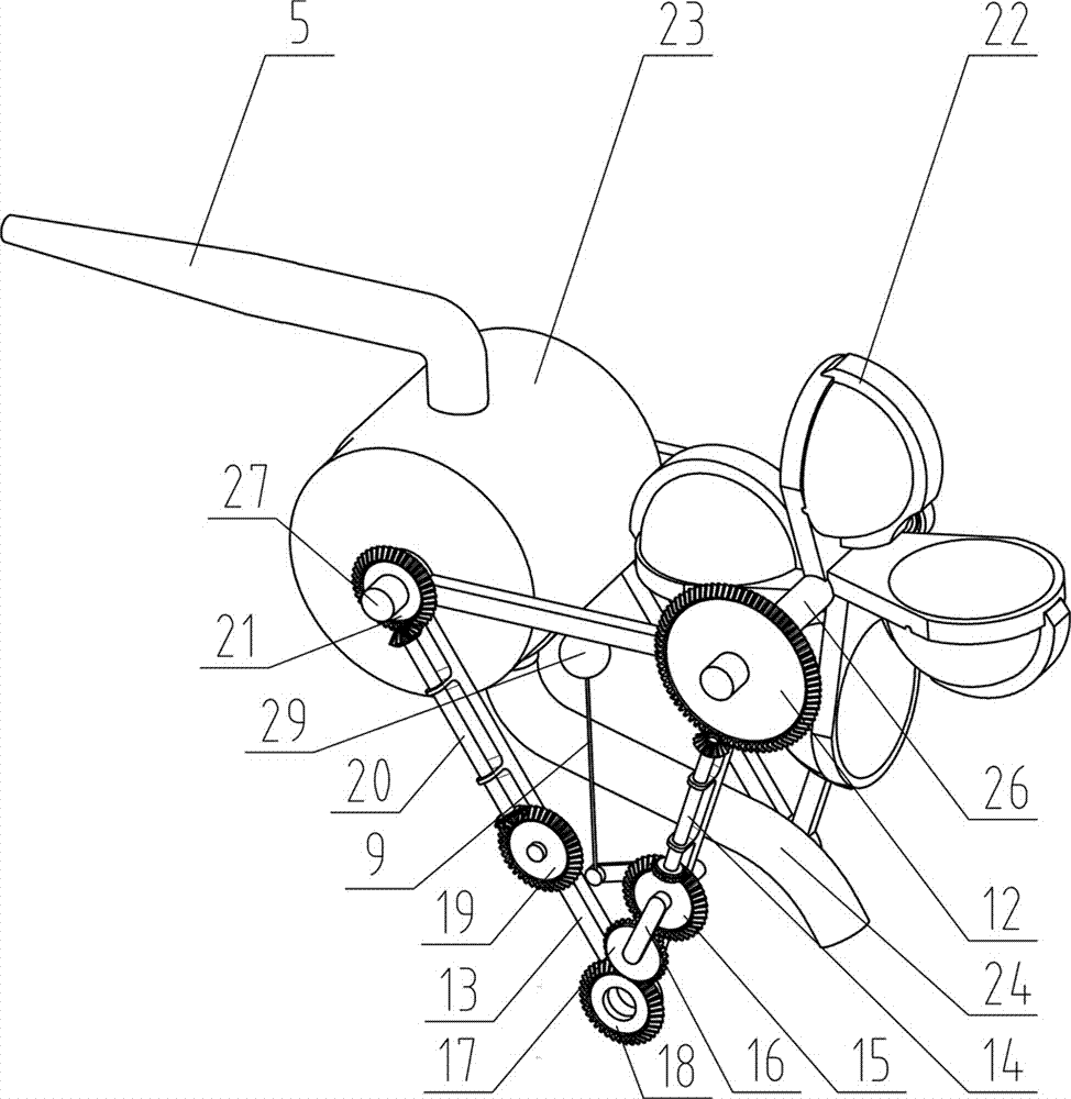
[0030] Such as Figure 1 to Figure 6As shown, a kind of semi-automatic fire fighting vehicle comprises shell 1, clapboard 8, the diversion pipe 2 that is arranged on shell 1 back top, support frame and semi-automatic transmission fire-fighting system, and described clapboard 8, support frame and semi-automatic transmission fire-fighting system are all Arranged in the casing 1, the casing 1 is arranged on the connecting shaft 11, the semi-automatic fire-fighting system is distributed on the second support frame 13, and the semi-automatic transmission fire-fighting system consists of the first gear 12, the first gear shaft 14, the second gear 15, The 3rd gear 17, the 4th gear 18, the 5th gear 19, the 2nd gear shaft 20, the 6th gear 21 and hydraulic turbine form, and described support frame comprises first support frame 25 and seco...


PUM


Abstract

The invention relates to a semi-automatic fire fighting truck. The semi-automatic fire fighting truck comprises a housing, a partition, a water guide tube arranged at the rear upper side of the housing, a supporting frame and a semi-automatic transmission fire fighting system, wherein the partition is used for dividing the housing into a transmission region and a water storage region; a water turbine and an outlet of the water guide tube are positioned in the water storage region of the housing; an outlet of the water guide tube faces towards the water turbine; the water turbine of the semi-automatic transmission fire fighting system is positioned in the water storage region of the housing, and the rest parts are positioned in the transmission region of the housing; the water turbine is transversely arranged between the first supporting frame and the second supporting frame; the semi-automatic transmission fire fighting system is connected with a self-priming pump through a transmission shaft; the self-priming pump is positioned in front inside the housing; the self-priming pump sleeves a transmission shaft; a crank is rotatably connected with a long rod which is vertically arranged; and the top end of the long rod is connected with a floating ball. The semi-automatic fire fighting truck adopts a mechanical structure to replace a fireman to get close to a fire scene to a greater extent; and a transmission device is engaged through a gear, so that the semi-automatic fire fighting truck is more reliable and stable.

Description

technical field [0001] The invention relates to the technical field of fire fighting equipment, in particular to a semi-automatic fire truck. Background technique [0002] With the rapid development of social economy, large-scale and complex fires are becoming more and more frequent, and it is becoming more and more difficult to extinguish fires and rescue personnel. In the face of modern fires, the combat performance of active fire trucks obviously cannot meet the needs, mainly in the following aspects: First, the sprayed fire extinguishing agent cannot give full play to its fire extinguishing efficiency. If it is lost, the fire extinguishing efficiency is not high. To extinguish a large fire, it is necessary to maintain the fire extinguishing concentration of the fire extinguishing agent in the combustion zone, and it is necessary to continuously spray the fire extinguishing agent, which often causes serious water damage and chemical pollution to the environment; secondly...

Claims


Application Information

Patent Timeline
Patent Type & Authority Applications(China)
IPC IPC(8): A62C27/00
CPCA62C27/00
Inventor 李辉尹甜甜丁召彬张延青景文静韩守印
Owner KAIFENG UNIV
Why Eureka
Try Eureka