Municipal landscaping soil environment-friendly repairing device

A landscaping and soil technology, applied in the restoration of polluted soil, grain treatment, etc., can solve the problems of development restrictions and impacts of polluted land, and achieve the effect of simple structure, good shock absorption effect, and easy handling

Inactive Publication Date: 2017-11-28
卢杰
0 Cites 59 Cited by

AI-Extracted Technical Summary

Problems solved by technology

Pollutants in abandoned land are like "uncertain time bombs", which have b...

Abstract

The invention discloses an environmental protection restoration device for municipal landscaping soil, which comprises a processing box, the processing box is a cylindrical body, a feeding pipe is arranged at the upper left end of the processing box, a feeding hopper is arranged at the upper end of the feeding pipe, and a feeding hopper is arranged at the upper end of the feeding pipe. There is a crushing roller in the bucket, a crushing motor is fixed in the middle of the upper end of the processing box, a crushing shaft is set at the output end of the crushing motor, movable crushing knives are arranged symmetrically on both sides of the crushing shaft, and several fixed crushing knives are arranged in an array inside the processing box. The knives, the fixed pulverizing knives and the movable pulverizing knives are distributed at cross intervals. The structure of the invention is simple and reasonable, the shock absorption effect is good, and it is easy to carry. The size of the soil particles when mixed with the remediation fluid helps to ensure the remediation effect of the soil, and the unqualified soil will enter the collection box, and then be sent back by the lifting cylinder, so as to realize the circular crushing of the soil, which has strong practicability.

Application Domain

Contaminated soil reclamationGrain treatments

Technology Topic

EngineeringLandscaping

Image

  • Municipal landscaping soil environment-friendly repairing device
  • Municipal landscaping soil environment-friendly repairing device
  • Municipal landscaping soil environment-friendly repairing device

Examples

  • Experimental program(1)

Example Embodiment

[0016] The technical solutions in the embodiments of the present invention will be clearly and completely described below with reference to the accompanying drawings in the embodiments of the present invention. Obviously, the described embodiments are only a part of the embodiments of the present invention, but not all of the embodiments. Based on the embodiments of the present invention, all other embodiments obtained by those of ordinary skill in the art without creative efforts shall fall within the protection scope of the present invention.
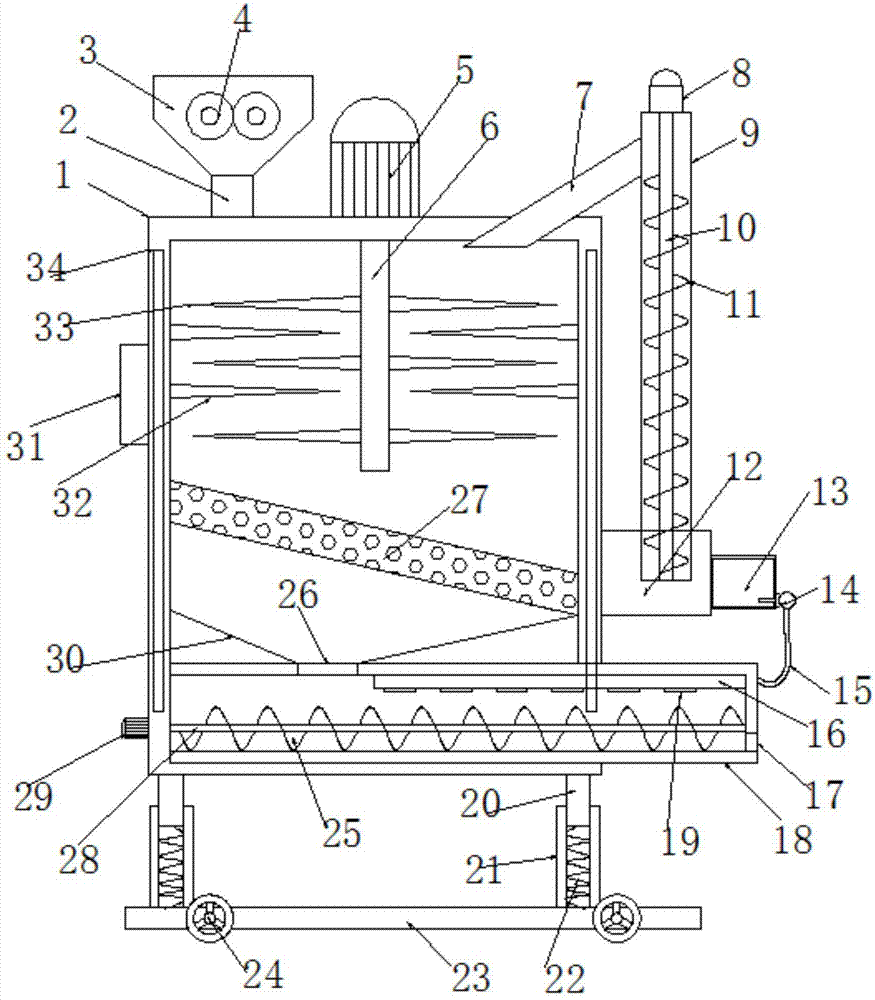
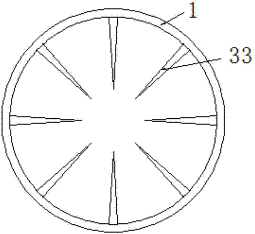
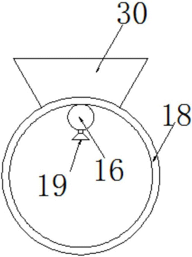
[0017] see Figures 1 to 3 , In the embodiment of the present invention, a municipal landscaping soil environmental protection restoration device includes a processing box 1, the processing box 1 is a cylindrical cylinder, the upper left end of the processing box 1 is provided with a feeding pipe 2, and the upper end of the feeding pipe 2 is provided A feeding hopper 3 is provided, and a pulverizing roller 4 is arranged in the feeding hopper 3. The function of the pulverizing roller 4 is to preliminarily pulverize the material. A pulverizing motor 5 is fixed in the middle position of the upper end of the processing box 1, and the output end of the pulverizing motor 5 is There is a pulverizing shaft 6, and movable pulverizing knives 33 are symmetrically arranged on both sides of the pulverizing shaft 6. Several fixed pulverizing knives 32 are distributed in an array inside the processing box 1. The motor 5 drives the pulverizing shaft 6 and the movable pulverizing knife 33 on the pulverizing shaft 6 to rotate, and further pulverizes the materials in the processing box 1 twice. To help pulverize the material, the processing box 1 below the pulverizing shaft 6 is provided with a filtering inclined plate 27 arranged in a high left and right low setting. The filtering inclined plate 27 is evenly distributed with screening holes. A collection box 12 is fixed on the box 1, and the collection box 12 communicates with the processing box 1. The upper end of the collection box 12 is provided with a lifting cylinder 9, the upper end of the lifting cylinder 9 is fixed with a lifting motor 8, and the output end of the lifting motor 8 is provided with a lifting screw 10, The outer side of the lifting screw 10 is provided with a spiral blade 11, and the upper left side of the lifting cylinder 9 is provided with a return pipe 7. The left end of the return pipe 7 is connected to the return port on the upper right side of the processing box 1, and the unqualified materials enter along the filter inclined plate 27. In the collection box 12, under the action of the lifting motor 8, the lifting screw 10 drives the helical blade 11 to rotate, and then lifts the material in the collection box 12, and then returns to the processing box 1 along the return pipe 7, so as to realize the removal of the material. The bottom of the processing box 1 below the filtering swash plate 27 is horizontally provided with a pushing cylinder 18, the left end of the pushing cylinder 18 is provided with a pushing motor 29, and the output end of the pushing motor 29 is provided with a pushing shaft 28, The surface of the pushing shaft 28 is provided with a pushing blade 25, and the lower right side of the pushing cylinder 18 is provided with a discharge port 17. The pushing motor 29 drives the pushing shaft 28 and the pushing blade 25 to rotate, and then pushes the material in the pushing cylinder 18. The material is pushed towards the discharge port 17, the upper left side of the push cylinder 18 is provided with a feed port 26, the upper end of the feed port 26 is fixed with a collection hopper 30, and the upper port of the collection hopper 30 is fixedly connected with the inner wall of the processing box 1. A spray pipe 16 is fixed on the inner wall of the upper right side of the barrel 18, and spray heads 19 are evenly distributed on the lower surface of the spray pipe 16. A repair liquid tank 13 is fixed on the right side of the collection box 12, and the liquid outlet end on the right side of the repair liquid tank 13 is connected The spray pump 14, the liquid outlet end of the spray pump 14 is connected to the spray pipe 16 through the liquid conduit 15. Under the action of the spray pump 14, the repair liquid in the repair liquid tank 13 enters the spray along the liquid conduit 15. Pipe 16, and then spray out through the nozzle 19, and then repair the soil, the lower end of the processing box 1 is provided with legs 20 symmetrically on both sides, the lower end of the legs 20 is slidingly sleeved with a support sleeve 21, and the support sleeve 21 is provided in the middle. There is a shock-absorbing spring 22, the upper and lower ends of the shock-absorbing spring 22 are respectively connected and fixed with the outrigger 20 and the support sleeve 21, and the support sleeve The lower end of 21 is connected and fixed with the base 23. The left and right sides of the base 23 are provided with rollers 24 which are convenient for the device to carry. The rollers 24 are self-locking rollers. 34. The spray pump 14, the crushing motor 5, the pushing motor 29 and the lifting motor 8 are electrically connected to the control panel 31.
[0018] It will be apparent to those skilled in the art that the present invention is not limited to the details of the above-described exemplary embodiments, but that the present invention may be embodied in other specific forms without departing from the spirit or essential characteristics of the invention. Therefore, the embodiments are to be regarded in all respects as illustrative and not restrictive, and the scope of the invention is to be defined by the appended claims rather than the foregoing description, which are therefore intended to fall within the scope of the claims. All changes within the meaning and scope of the equivalents of , are included in the present invention. Any reference signs in the claims shall not be construed as limiting the involved claim.
[0019] In addition, it should be understood that although this specification is described in terms of embodiments, not each embodiment only includes an independent technical solution, and this description in the specification is only for the sake of clarity, and those skilled in the art should take the specification as a whole , the technical solutions in each embodiment can also be appropriately combined to form other implementations that can be understood by those skilled in the art.

PUM

no PUM

Description & Claims & Application Information

We can also present the details of the Description, Claims and Application information to help users get a comprehensive understanding of the technical details of the patent, such as background art, summary of invention, brief description of drawings, description of embodiments, and other original content. On the other hand, users can also determine the specific scope of protection of the technology through the list of claims; as well as understand the changes in the life cycle of the technology with the presentation of the patent timeline. Login to view more.

Similar technology patents

Photoelectric sensor for position of sun

InactiveCN101650173AEffective tracking range expandedSimple structure
Owner:WUHAN UNIV OF TECH

Magnetic cooling apparatus and control method thereof

ActiveUS20130180263A1simple structure
Owner:SAMSUNG ELECTRONICS CO LTD

Dual-Drivetrain of Power-Assist Vehicle

InactiveUS20100181130A1enhance uphill momentumsimple structure
Owner:CHOU WEN CHENG

Classification and recommendation of technical efficacy words

  • Simple structure
  • good shock absorption

Anti-shock damping safety seat

Owner:CHONGQING TECH & BUSINESS INST

Robot damping device good in damping effect

Owner:GANZHOU YANSHUNFEI TECH CO LTD

Drill bit for oil-gas field exploration

InactiveCN107130920Agood shock absorptionEasy replacement
Owner:陕西舜洋电子科技有限公司
Why Eureka
Try Eureka