Method for increasing plane target utilization rate in magnetron sputtering coating process
A magnetron sputtering coating and planar target technology, which is applied in the field of magnetron sputtering coating, can solve the problems of waste of planar target materials and high film manufacturing costs, etc., and achieve increased etching area, increased electronic activity, and electronic Effect of exercise zone improvement
- Summary
- Abstract
- Description
- Claims
- Application Information
AI Technical Summary
Problems solved by technology
Method used
Image

Examples
Embodiment 1
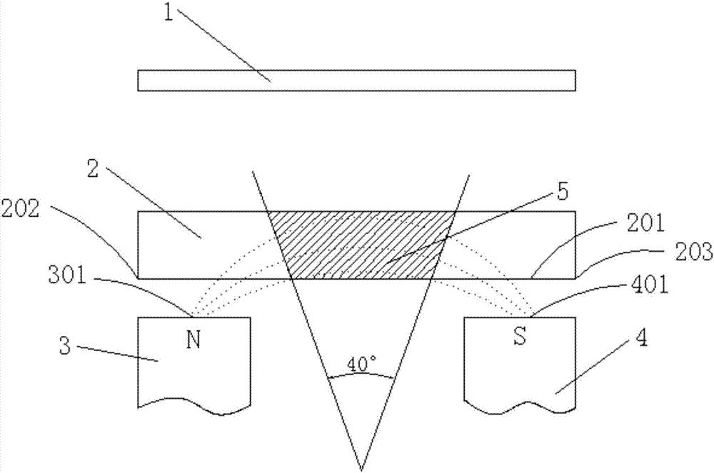
[0029] Such as Figure 5 and Figure 6 As shown, the two rows of magnets are rotated 45° towards the middle of the planar target 2, so that the N-pole magnetic pole surface 301 of one row of magnets and the S-pole magnetic pole surface 401 of the other row of magnets are respectively 45° from the first surface 201 of the planar target 2. ° angle tilt. This arrangement of magnets makes the magnetic induction intensity of the use area of the planar target 2 stronger than that of the prior art, and the electron activity in the sputtering area increases, and the movement area 5 of a large number of electrons is about a 50° arc range, and the etching area of the planar target 2 6 is about a 50° arc range, the etching area 6 increases, and the utilization rate of the planar target 2 is about 35%-40%, which is 40%-60% higher than the utilization rate of the planar target 2 in the prior art.
Embodiment 2
[0031] Rotate the two rows of magnets towards the middle of the planar target 2 by 5°, so that the N-pole magnetic pole surface 301 of one row of magnets and the S-pole magnetic pole surface 401 of the other row of magnets are respectively inclined at an angle of 5° to the first surface 201 of the planar target 2 . This arrangement of magnets makes a large number of electron movement areas 5 about 41 ° arc range, planar target 2 sputter etching area 6 is about 41 ° arc range, planar target 2 utilization rate is about 26%, relative to The improvement of planar target 2 in the prior art is 4%.
Embodiment 3
[0033] Rotate the two rows of magnets towards the middle of the planar target 2 by 60°, so that the N-pole magnetic pole surface 301 of one row of magnets and the S-pole magnetic pole surface 401 of the other row of magnets are respectively inclined at an angle of 60° to the first surface 201 of the planar target 2 . This arrangement of magnets makes a large number of electron movement areas 5 about 42° arc range, planar target 2 sputtering etching area 6 is about 42° arc range, planar target 2 utilization rate is about 28%, relatively Compared with the prior art, the utilization rate of the planar target 2 has increased by 12%.
[0034]By changing the arrangement structure of the magnet relative to the planar target 2, the distribution of the magnetic field is changed, so that the magnetic induction intensity of the magnetic field passing through the use area of the planar target 2 is enhanced, the activity of electrons in the sputtering area is increased, and the movement ...
PUM
 Abstract
Description
Claims
Application Information
 - R&D
- Intellectual Property
- Life Sciences
- Materials
- Tech Scout
- Unparalleled Data Quality
- Higher Quality Content
- 60% Fewer Hallucinations
Browse by: Latest US Patents, China's latest patents, Technical Efficacy Thesaurus, Application Domain, Technology Topic, Popular Technical Reports.
© 2025 PatSnap. All rights reserved.Legal|Privacy policy|Modern Slavery Act Transparency Statement|Sitemap|About US| Contact US: help@patsnap.com