
Vibration reduction device of high-speed rotating shaft system

A technology of a high-speed rotating shaft and a vibration damping device, which is applied in the field of vibration reduction and noise reduction, can solve the problems of limiting particle collision, frictional energy consumption, poor vibration reduction effect, and poor vibration reduction effect of particle dampers, so as to increase particle damping. effect, the effect of increasing the magnetic induction intensity

Inactive Publication Date: 2015-04-08
JIANGSU UNIV OF SCI & TECH
View PDF11 Cites 14 Cited by
  • Summary
  • Abstract
  • Description
  • Claims
  • Application Information

AI Technical Summary

Problems solved by technology

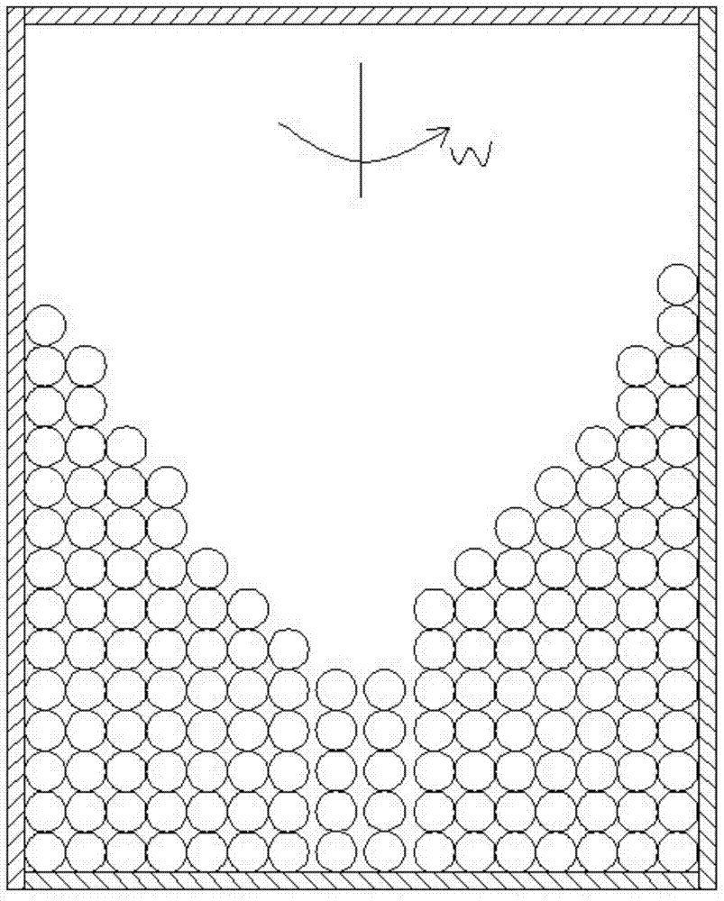
However, the particle damping and vibration reduction device has poor vibration reduction effect on high-speed rotating devices. The reason is that the centrifugal force generated when the structure rotates makes the particles in a compacted state, which greatly limits the collision and friction energy consumption of the particles, resulting in particle dampers. The vibration effect is very poor, such as a kind of hollow shaft particle damper mentioned in the patent No. CN101725656A

Method used


Image

  • Vibration reduction device of high-speed rotating shaft system
  • Vibration reduction device of high-speed rotating shaft system
  • Vibration reduction device of high-speed rotating shaft system

Examples


Embodiment Construction

[0021] The present invention will be further described below in conjunction with the accompanying drawings.

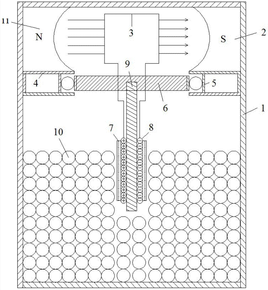
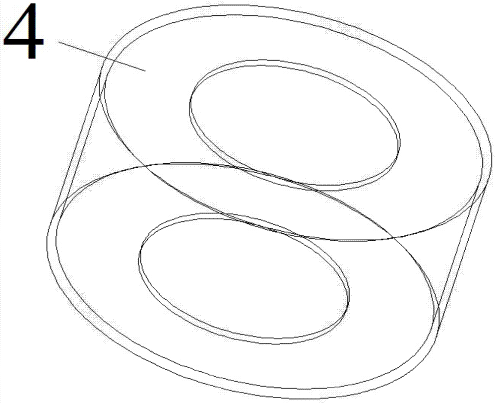
[0022] Such as Figure 1 to Figure 3 As shown, a vibration damping device for a high-speed rotating shaft system of the present invention includes a particle damper housing 1 filled with particles, and the two sides of the top of the particle damper housing 1 are respectively installed There is a first magnet 2 and a second magnet 11 opposite in polarity to the first magnet, a hollow casing 4 is fixedly installed below the first magnet 2 and the second magnet, and a bearing 5 is installed in the hollow casing 4, and the inner part of the bearing 5 The ring is connected to the supporting cylinder 6, and the iron core 9 is fixedly installed in the supporting cylinder 6, and the energized coil 8 is wound on the iron core 9, and the energized coil 8 is connected with the metal ring 3 located between the first magnet 2 and the second magnet.

[0023] In the present inventi...


PUM


Abstract

The invention discloses a vibration reduction device of a high-speed rotating shaft system. The device comprises a particle damper shell, wherein particles are filled in the particle damper shell; a first magnet and a second magnet which is reverse to the first magnet in polarity are arranged on the two sides of the top of the particle damper shell respectively; a hollow shell is fixedly arranged on the lower side of the first magnet and the second magnet; a bearing is arranged in the hollow shell; an inner ring of the bearing is connected with a supporting cylinder; an iron core is fixedly arranged in the supporting cylinder; an electrified coil is wound on the iron core and is connected with a metal coil in the middle of the first magnet and the second magnet. According to the vibration reduction device of the high-speed rotating shaft system, a magnetic field is generated by flowing current produced by an electromagnetic induction system through the electrified coil, and centrifugal force stressed by the particles is counteracted by magnetic field force to eliminate the phenomenon of marginalized squeezing of the particles, so a best vibration reduction state is achieved.

Description

technical field [0001] The invention relates to a vibration damping device, in particular to a vibration damping device for a high-speed rotating shaft system, and belongs to the technical field of vibration reduction and noise reduction. Background technique [0002] The power transmission shafting is a multi-degree-of-freedom vibration system that transmits torque through rotation and excites the vehicle body to vibrate. These vibrations will not only greatly reduce the ride comfort of the vehicle, but also produce obvious external noise. Under the action of various external excitations, if the excitation frequency generated by these excitations is very close to the natural frequency of the transmission shaft, severe resonance will occur, and when this vibration reaches a certain level, it will even cause fatigue of vehicle components Damage will lead to major accidents such as shaft fracture. Existing shafting dampers include viscous fluid dampers and magneto-rheologica...

Claims


Application Information

Patent Timeline
Patent Type & Authority Applications(China)
IPC IPC(8): F16F7/01F16F6/00
CPCF16F6/00F16F7/015
Inventor 夏兆旺魏守贝袁秋玲方媛媛张文陈志超丁玉鑫刘文豪
Owner JIANGSU UNIV OF SCI & TECH
Learn More