Door stop structure

A door suction and slideway technology, applied in door/window fittings, building structures, buildings, etc., can solve the problems of no buffer structure, device damage, loud noise, etc., and achieve the effect of reducing the length

Pending Publication Date: 2017-11-28
张秦鸣
View PDF8 Cites 6 Cited by
  • Summary
  • Abstract
  • Description
  • Claims
  • Application Information

AI Technical Summary

Problems solved by technology

[0004] Although the door suction combination device in the above patent document can realize the suction of the sliding door, it does not have a buffer structure, and the device is easily damaged due to excessive impact force during the door closing process, and it will also generate relatively large noise; The applicant previously applied for an improved damping and buffering door suction structure; however, it was found in the course of use that the cylinder body and telescopic rod of the hydraulic damper are relatively long, and to achieve sufficient buffering strength, the entire door suction structure must be The volume will be relatively large, making the overall installation limited and prone to interference

Method used


Image

  • Door stop structure
  • Door stop structure
  • Door stop structure

Examples


Embodiment 1

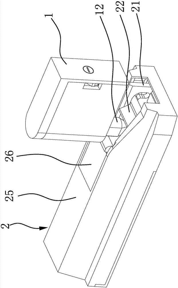
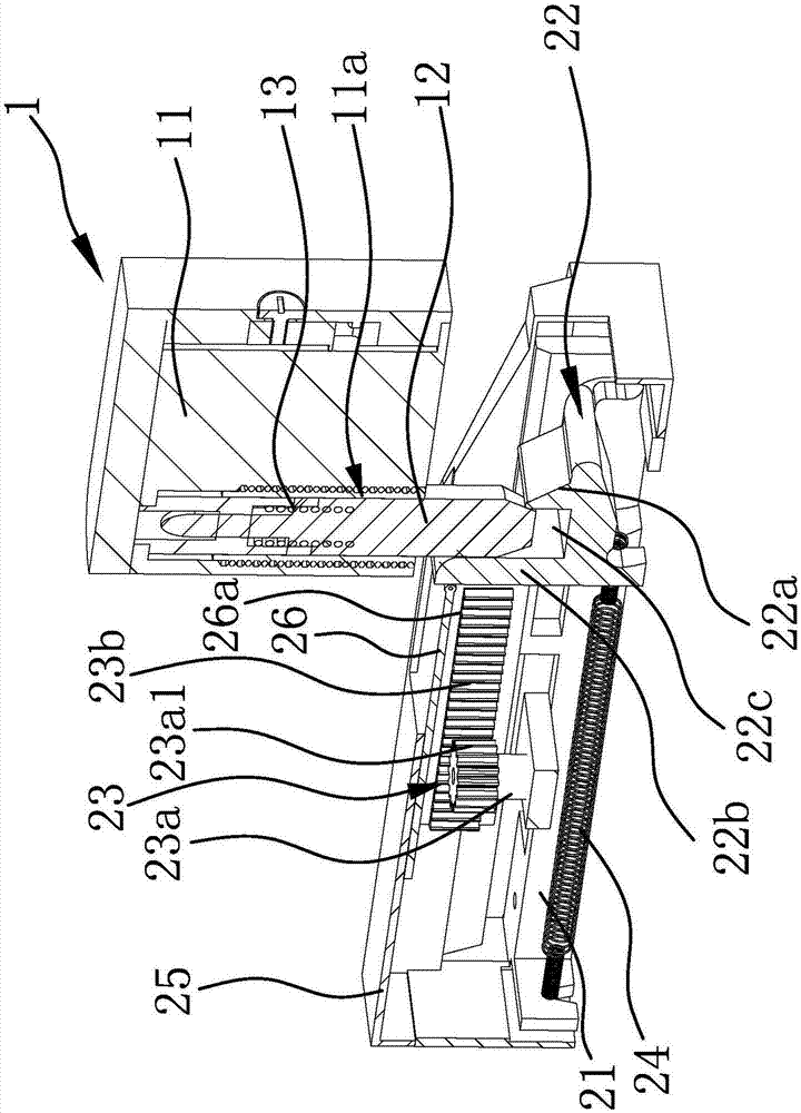
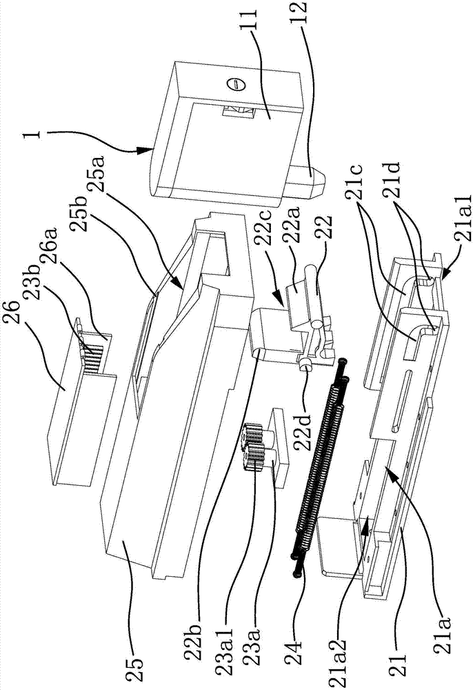
[0042] Such as figure 1 , figure 2 and image 3 As shown, the door suction structure includes a positioning piece 1 and a buffer assembly 2 arranged oppositely. The positioning piece 1 has a snap joint 12; the buffer assembly 2 includes a mounting seat 21 and a return elastic member 24, and the mounting seat 21 is provided with a slideway 21a. , the slideway 21a is provided with a trigger slider 22 capable of reciprocating movement, the trigger slider 22 has a clamping part 22a connected with the clamp joint 12; It is the suction end 21a2, and the clamping joint 12 can engage or disengage between the clamping end 21a1 of the slideway 21a and the clamping part 22a of the trigger slider 22; The sliding block 22 is a rotation damping structure 23 that generates resistance when it moves from the locking end 21a1 of the slideway 21a to the suction end 21a2; The elastic restoring force of the joint end 21a2. Specifically, the mounting base 21 is provided with a housing 25, the ...

Embodiment 2

[0046] Such as Figure 4 and Figure 5 As shown, this embodiment is substantially the same as Embodiment 1, the difference is that the rotation damping structure 23 in this embodiment includes a rack 23b fixed on the mounting base 21 and a rotating body 23a connected to the trigger slider 22 The rotating body 23a has buffer damping and is hinged with the trigger slider 22 through the connecting plate; the rotating body 23a has a gear 23a1; the rack 23b is arranged along the length direction of the slideway 21a, and the gear 23a1 is meshed with the rack 23b; 23a is connected to the trigger slider 22 and can move accordingly, the rack 23b is fixed on the mounting seat 21, and the snap joint 12 on the positioning part 1 pushes the trigger slider 22 from the locking end 21a1 of the slideway 21a to the suction end 21a2 When moving, the rotating body 23a and the gear 23a1 on the rotating body 23a are driven to move, the rack 23b meshes with the gear 23a1 on the rotating body 23a, a...

Embodiment 3

[0048] Such as Figure 6 and Figure 7 As shown, this embodiment is substantially the same as Embodiment 2, the difference is that the specific installation position of the rack 23b in the rotation damping structure 23 and the specific structure of the rotating body 23a are different; the number of racks 23b in this embodiment is two and are respectively located on both sides of the slideway 21a. The rack 23b is arranged along the length direction of the slideway 21a. The rotating body 23a is hinged with the trigger slider 22. The rotating body 23a has a horizontal setting and both ends pass through the rotating body 23a. The external rotating shaft 23a2; the two ends of the rotating shaft 23a2 have a gear 23a1 which is in transmission connection with the rack 23b. When the snap joint 12 on the positioning member 1 pushes the trigger slider 22 to move from the locking end 21a1 of the slideway 21a to the suction end 21a2, it drives a rotating body 23a to move, and both ends of...


PUM


Abstract

The invention provides a door stop structure, belongs to the technical field of locating apparatuses, and solves the problem that an existing door stop structure is poor in buffer effect. The door stop structure comprises a locating part and a buffer assembly which are arranged oppositely; a locking head is arranged on the locating part; the buffer assembly comprises a mounting seat and a reset elastic part, a slideway is arranged on the mounting seat, a triggering slide block which can reciprocate is arranged on the slipway, and the triggering slide block has a locking portion connected to the locking head; one end, facing the locating part, of the slideway is a locking end while the other end is an actuation end; the locking head can be locked on or separated from the locking end of the slideway and the locking portion of the triggering slide block; a rotary damping structure capable of generating resistance in a process that the triggering slide block moves from the locking end to the actuation end of the slideway is arranged between the mounting seat and the triggering slide block; and the reset elastic part has an elastic reset force which pulls the triggering slide block from the locking end to the actuation end of the slideway. The door stop structure improves the compactness while the buffer effect of the door stop structure is guaranteed.

Description

technical field [0001] The invention belongs to the technical field of positioning devices and relates to a door suction structure. Background technique [0002] When the doors and windows are opened or closed, it is necessary to prevent them from generating excessive impact to avoid damage and noise caused by severe collisions. After the doors and windows are opened, it is also necessary to keep them in a stable state to prevent abnormal movements caused by wind or external force touch , Most of the windows use manual control of the buffering force, and then achieve the above purpose through positioning pins or locks, and the door panels usually use door suction to solve this problem. However, the existing door suction products on the market generally have problems such as poor cushioning effect, too small suction force, and easy damage. [0003] Chinese patent (notification number: CN2648010, date of announcement: 2004-10-13) discloses a combination device of a sliding do...

Claims


Application Information

Patent Timeline
IPC IPC(8): E05C17/48E05F5/08E05F5/06
CPCE05C17/48E05F5/06E05F5/08
Inventor 张秦鸣
Owner 张秦鸣
Why Eureka
Try Eureka