A High Precision Braking Mechanism

A brake mechanism, high-precision technology, applied in the direction of brake actuators, gear transmission mechanisms, mechanical equipment, etc., can solve the problems of low space utilization, difficult to ensure accuracy, large braking torque, etc., to achieve volume reduction and weight, overcome the poor braking effect, and reduce the effect of braking torque

Active Publication Date: 2022-05-20
HEBEI UNIV OF TECH
View PDF15 Cites 0 Cited by
  • Summary
  • Abstract
  • Description
  • Claims
  • Application Information

AI Technical Summary

Problems solved by technology

[0003] The above-mentioned brake requires a larger coil to generate sufficient magnetic force, and requires a relatively large elastic force of the spring, and the structure is complicated; Larger heat has higher requirements for heat dissipation. If it is applied to a high-speed rotating mechanism, how to solve the problem of heat dissipation is a difficult problem; because the above-mentioned brake uses the principle of friction braking, the braking torque is relatively small under a certain volume limit; the above-mentioned The structure of the brake has complex structure, heavy weight, large volume, low interchangeability, high cost, and difficulty in heat dissipation
Traditional excitation brakes, such as Miki Pulley’s excitation brakes, separate models, need to ensure a fixed gap between the stator and the rotor during installation. This gap is generally 0.2-0.5mm. Because it is very small, it is difficult to ensure its Accuracy, and this accuracy needs to be guaranteed by the customer. The seller is not responsible for the assembly. During the movement, a slightly larger axial movement may interfere with this gap, making the stator and the rotor come into contact, and the installation is inconvenient.
For the one-piece brake, although there is no need to guarantee the clearance, it is expensive, about 500 yuan, and the cost is relatively high, and the structure is complicated. Since it is one-piece, if there is a problem during use, it is difficult to pass. Replacement of damaged parts to achieve the purpose of maintenance, more is the need to replace a new brake
[0004] In addition, the Chinese patent application number 2015108280611 discloses a brake device, which uses an electromagnetic switch to block the turntable to achieve braking, but the connection between the brake disk and the shaft is a jackscrew connection, and the installation is not reliable; and the teeth of the disk are strips In the braking process, it is easy to slip radially with the electromagnet, resulting in braking failure; there is no harmonic reducer and other similar large reduction ratio reduction mechanisms in the components of the braking mechanism, and its braking accuracy It is not high, and the required braking torque is relatively large; the electromagnetic switch is connected to the stator through an iron sheet, which is low in strength, unstable, and easily damaged; the axial distance occupied by the electromagnetic switch is relatively large, and the electromagnetic switch needs to be reserved for its electromagnet. The distance of the limit height position that can be reached, the space utilization rate is low

Method used


Image

  • A High Precision Braking Mechanism
  • A High Precision Braking Mechanism
  • A High Precision Braking Mechanism

Examples


Embodiment 1

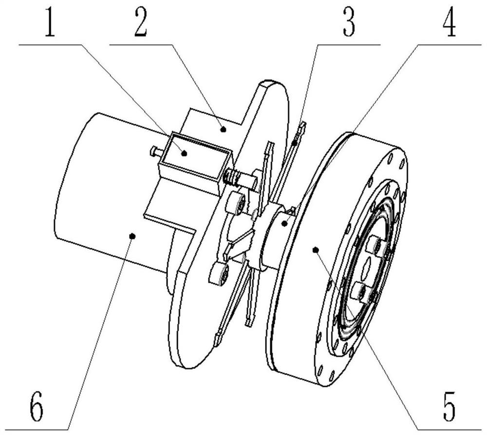
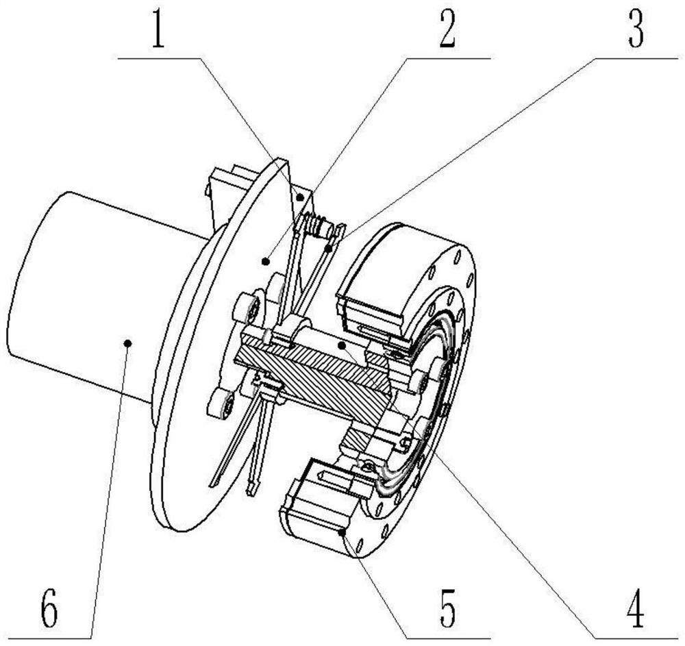
[0033] The high-precision braking mechanism of this embodiment includes a brake switch 1, a brake disc 3, a switch connecting frame 3, a rotating shaft 4 and a driving device 6; Rotational movement; the driving device is connected to the input end of the rotating shaft, and drives the rotating shaft to perform rotational movement, so that the rotating shaft 4 rotates relative to the switch connection frame 2; the brake switch is installed on the switch connection frame;

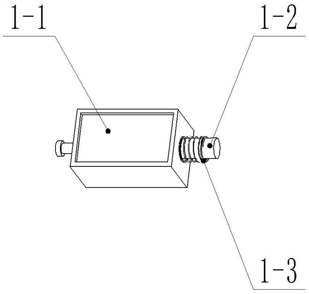
[0034] The brake switch 1 includes an electromagnetic switch 1-1, an iron core 1-2 and a return spring 1-3, the electromagnetic switch 1-1 is fixed on the switch connecting frame 2, and the iron core 1-2 is inserted into the electromagnetic In the cylindrical through hole in the center of the switch 1-1, the connection between the electromagnetic switch 1-1 and the iron core 1-2 is completed by the return spring 1-3; the electromagnetic switch 1-1 is fixed by M2 screws On the switch connecting plate 2, the el...


PUM


Abstract

The invention relates to a high-precision braking mechanism, which includes a brake switch, a brake disc, a switch connection frame, a rotating shaft and a driving device; the driving device is connected to the input end of the rotating shaft, and is characterized in that the brake disc It is installed on the shoulder of the rotating shaft and rotates with the rotating shaft; the brake switch is installed on the switch connecting frame; the brake switch includes an electromagnetic switch, a return spring and an iron core, and the iron core is inserted into the electromagnetic The connection between the electromagnetic switch and the iron core is completed by the return spring; the brake disc includes a fixed base and six disc teeth with the same structure; the six disc teeth are used to fix the base The base is evenly distributed on the side of the cylinder of the fixed base, and the width of each tooth is gradually reduced from the connection end of the fixed base to the end of the tooth; the ends of the teeth are symmetrically arranged with V-shaped grooves on both sides; The fixed base is cylindrical with a bottom end capped.

Description

technical field [0001] The invention relates to the technical field of transmission control, in particular to a high-precision braking mechanism. Background technique [0002] The brakes or braking systems currently in use basically adopt the structure of electromagnets and springs, and the brake disc is in the shape of a ring, which is mainly braked by friction braking. The motion system is powered on, and the electromagnetic brake coil is activated. Electricity, magnetic force is generated, the armature pulls in, overcomes the tension of the spring to separate the stator of the brake from the rotor, and the rotating shaft operates normally; the motion system is powered off, and the electromagnetic brake coil is also powered off, and the armature is separated from the electromagnet under the action of spring tension , and make the rotor of the brake tightly press the stator, and the rotating shaft is braked due to the friction between the stator and the rotor to stop, so as...

Claims


Application Information

Patent Timeline
Patent Type & Authority Patents(China)
IPC IPC(8): F16D65/14F16D121/20
CPCF16D65/14F16D2121/20Y02P70/10
Inventor 刘璇卜必正张建华张明路蔡灿许晓林李克祥
Owner HEBEI UNIV OF TECH
Why Eureka
Try Eureka