Measurement system ad method of amplitude of resonant type scanning mirror

A measurement system and scanning mirror technology, applied in the direction of measuring devices, measuring ultrasonic/sonic/infrasonic waves, instruments, etc., can solve the problems of low measurement accuracy and achieve the effects of easy amplitude accuracy, improved measurement accuracy, and easy guarantee of accuracy

Active Publication Date: 2017-11-28
XI AN ZHISENSOR TECH CO LTD
View PDF7 Cites 9 Cited by
  • Summary
  • Abstract
  • Description
  • Claims
  • Application Information

AI Technical Summary

Problems solved by technology

[0006] In order to solve the problem of low measurement accuracy when using a photodetector to measure the amplitude of the scanning mirror to be tested, the present invention provides a system and method for accurately measuring the amplitude of the resonant scanning mirror to be tested. Place a single laser and several photodetectors side by side to measure the amplitude

Method used


Image

  • Measurement system ad method of amplitude of resonant type scanning mirror
  • Measurement system ad method of amplitude of resonant type scanning mirror
  • Measurement system ad method of amplitude of resonant type scanning mirror

Examples


Embodiment 1

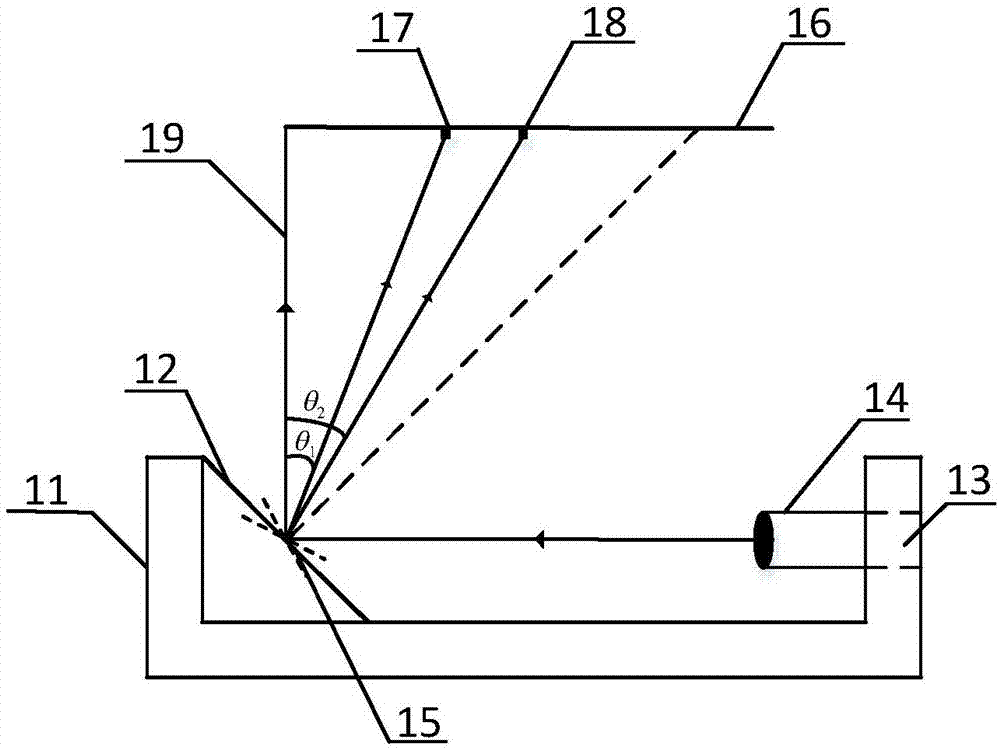
[0057] In this embodiment, based on the condition that the center scan line 19 of the scanning mirror under test is perpendicular to the plane of the photosensitive fixed scale 16, two photodetectors are used to realize the measurement of the amplitude of the scanning mirror under test.

[0058] From figure 1 It can be seen that the measurement system mainly includes a laser 14, a fixture 11, a photosensitive fixed scale 16, and a first photodetector 17 and a second photodetector 18 set on the photosensitive fixed scale. The fixture 11 is provided with a The scanning mirror fixing frame 12 is fixed to the laser fixing hole 13, the scanning mirror 15 to be tested is fixed on the scanning mirror fixing frame 12 of the tooling fixture, and the laser 14 is fixed in the laser fixing hole 13.

[0059] The laser light is incident on the center of the scanning mirror 15 to be tested. During the vibration of the scanning mirror 15 to be tested, the light is reflected to form a scanning track...

Embodiment 2

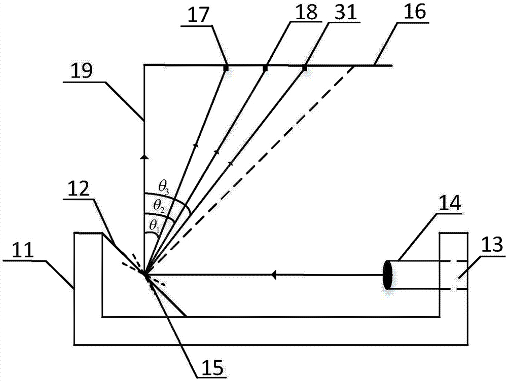
[0071] In this embodiment, based on the condition that the center scan line 19 of the scanning mirror under test is perpendicular to the plane of the photosensitive fixed scale 16, three photodetectors are used to realize the measurement of the amplitude of the scanning mirror under test.

[0072] From image 3 It can be seen that the measurement system mainly includes a fixture 11, a photosensitive fixed scale 16, and a first photodetector 17, a second photodetector 18, and a third photodetector 31 arranged on the photosensitive fixed scale. The fixture 11 The upper relative positions are respectively provided with the scanning mirror fixing frame 12 to be tested and the laser fixing hole 13, the scanning mirror to be tested 15 is fixed on the scanning mirror fixing frame 12 to be tested in the fixture, and the laser 14 is fixed in the laser fixing hole 13. This embodiment is different from the first embodiment in that a third photodetector 31 is added.

[0073] The laser light is...

Embodiment 3

[0085] In this embodiment, based on the condition that the center scan line 19 of the scanning mirror under test and the plane of the photosensitive fixed scale 16 are at an angle α, four photodetectors are used to realize the measurement of the amplitude of the scanning mirror under test.

[0086] From Figure 5 It can be seen that the measurement system mainly includes a tooling fixture 11, a photosensitive fixed scale 16, and a first photodetector 17, a second photodetector 18, a third photodetector 31, and a fourth photodetector arranged on the photosensitive fixed scale. In the fixture 51, the scanning mirror fixing frame 12 to be tested and the laser fixing hole 13 are respectively provided on the relative positions of the fixture 11, the scanning mirror under test 15 is fixed on the scanning mirror fixing frame 12 of the fixture to be tested, and the laser 14 is fixed on the laser fixing In the hole 13, the difference between this embodiment and the second embodiment is tha...


PUM


Abstract

The invention belongs to the field of micro-opto-electro-mechanical systems and particularly relates to a measurement system ad method of the amplitude of a resonant type scanning mirror. The system comprises a laser, a tool clamp used for fixing the laser and a to-be-measured scanning mirror, a photosensitive fixed scale and at least two photoelectric detectors arranged on the photosensitive fixed scale. Laser rays irradiate into the center of the to-be-measured scanning mirror. Incidence light is reflected by the to-be-measured scanning mirror so that scanning paths are formed. The photoelectric detectors capture electrical signals of respective position of reflection light generation marks. According to the electrical signals obtained in the step 3 and the position relation of the photoelectric detectors, the vibration amplitude of the to-be-measured scanning mirror is obtained. By use of the photoelectric detectors for detection, the measurement quantity of the system is reduced and a problem of low measurement precision when the photoelectric detectors are used for measuring and calculating the amplitude of the to-be-measured scanning mirror is solved.

Description

Technical field [0001] The invention belongs to the field of micro-optical electromechanics (MOEMS), and specifically relates to a resonant scanning mirror amplitude measurement system and method. Background technique [0002] The resonant MEMS scanning mirror under test has the advantages of large scanning angle, low driving power consumption, small inertia, small size, light weight, and easy integration. It has a wide range of requirements in laser sensing, laser projection, laser imaging and other applications. Key components in laser applications. [0003] The vibration amplitude of the resonant MEMS scanning mirror under test is more sensitive to its driving voltage and external environment such as temperature, humidity, and air pressure. Some applications such as lidar and laser projection require higher amplitude accuracy of the scanning mirror under test. In order to meet the high-amplitude accuracy requirements, the scanning mirror under test will integrate an angular pos...

Claims


Application Information

Patent Timeline
Patent Type & Authority Applications(China)
IPC IPC(8): G01H9/00
Inventor 夏长锋何耀军谈鹏郑文会乔大勇
Owner XI AN ZHISENSOR TECH CO LTD
Why Eureka
Try Eureka