Vibration mechanism, receiver and assembly method of receiver

An assembly method and technology of vibration mechanism, applied in the direction of sensors, electrical components, etc., can solve the problems of low reliability of vibration mechanism and difficult assembly, and achieve high strength, ensure normal installation, and high connection strength.

Pending Publication Date: 2017-11-28
SUZHOU YICHUAN TECH CO LTD
View PDF0 Cites 2 Cited by
  • Summary
  • Abstract
  • Description
  • Claims
  • Application Information

AI Technical Summary

Problems solved by technology

[0005] Therefore, the technical problem to be solved by the present invention lies in the low reliability of the vibration mechanism between the armature of the moving iron receiver and the vibration plate and the difficulty of assembly

Method used


Image

  • Vibration mechanism, receiver and assembly method of receiver
  • Vibration mechanism, receiver and assembly method of receiver
  • Vibration mechanism, receiver and assembly method of receiver

Examples


Embodiment 1

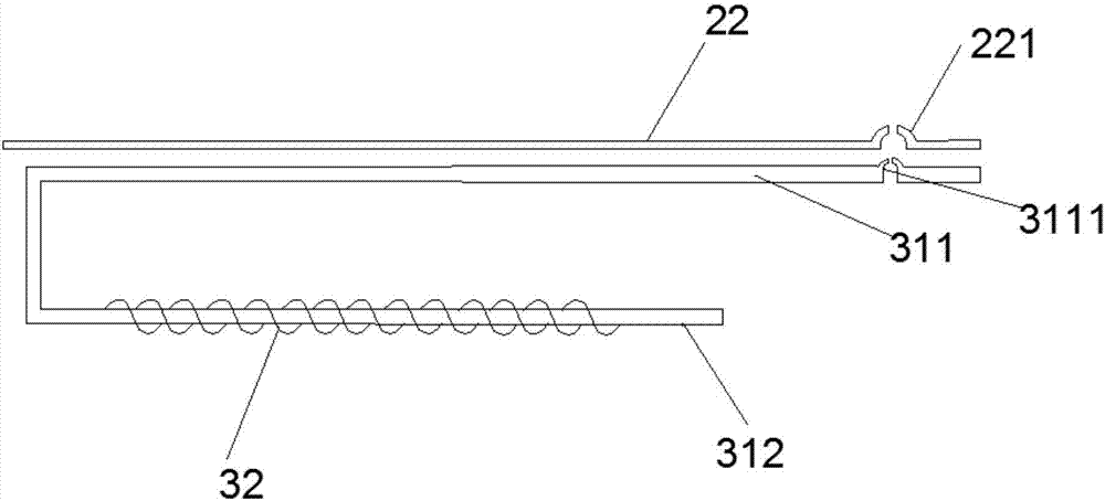
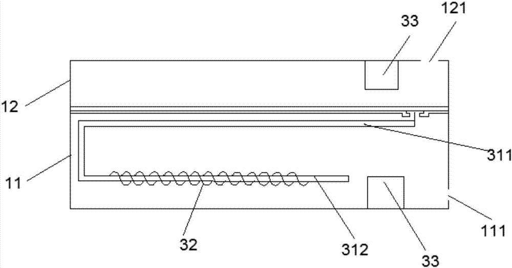
[0061] This embodiment provides a receiver, such as image 3 As shown, it includes a housing 1 , a sound membrane mechanism 2 and a vibration mechanism 3 . The housing 1 has a first housing 11 formed with a first chamber 13 and a second housing 12 formed with a second chamber 14, the first housing 11 and the second housing 12 can be buckled to form an inner chamber , wherein the first housing 11 is provided with a tuning hole 111 , and the second housing 12 is provided with a sound outlet 121 .

[0062] The acoustic membrane mechanism 2 divides the inner cavity into a first chamber 13 and a second chamber 14, wherein the acoustic membrane mechanism 2 can be arranged between the first housing 11 and the second housing 12, or be stuck in the first housing In body 11. The sound membrane mechanism 2 in this embodiment includes a fixed frame 21, a vibrating plate 22 and a sound membrane 23, the fixed frame 21 is connected to the housing 1, and the fixed frame 21 is fixedly instal...

Embodiment 2

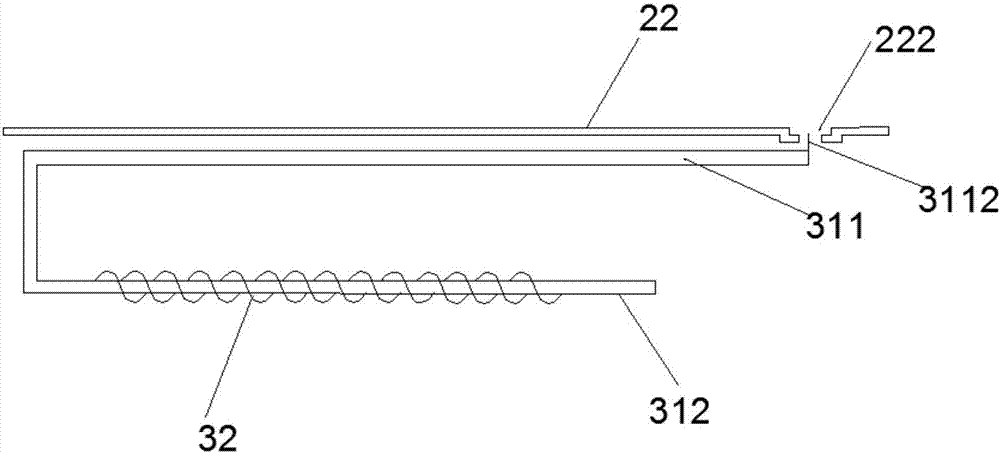
[0084] Embodiment 2 provides a receiver, which is mainly different from Embodiment 1 in that the fixing unit is arranged in a different way, and the rest of the structure of the receiver in Embodiment 2 is the same as Embodiment 1.

[0085] Such as figure 2 As shown, the fixing unit in this embodiment is a protrusion and a groove whose shape and size match. Wherein the end of the first arm unit 311 is provided with a sheet-like protrusion 3112, the opposite side of the vibrating plate 22 to the sound membrane 23 is provided with a groove that is sunken toward the armature, and the bottom of the groove is provided with a fixing hole 222. The shape protrusion 3112 is inserted into the fixing hole 222 . And the two are fixedly connected by injecting adhesive into the groove or welding and fixing the sheet-shaped protrusion in the groove, thereby ensuring the connection strength of the two and improving the connection reliability.

[0086] As an alternative embodiment, the surfac...


PUM


Abstract

The invention discloses a vibration mechanism, a receiver and an assembly method of the receiver. The receiver of the invention comprises: a casing, an inner cavity is formed in the casing; a sound film mechanism; a vibration mechanism, and the vibration mechanism includes an electromagnet unit and a permanent magnet; the electromagnet and the vibrating plate are provided with a matching fixing unit, and the electromagnet unit and the vibrating plate are fixedly connected through the fixing unit. In the receiver of the invention, the connection structure between the armature and the vibrating plate is stable, and the problem of sound distortion is avoided.

Description

technical field [0001] The invention relates to the field of electromagnetic receivers, in particular to a vibration mechanism, a receiver and an assembly method for the receiver. Background technique [0002] Electromagnetic receivers are widely used in portable electronic devices such as mobile phones, notebook computers, and hearing aids. With the rapid development of these portable electronic devices, people have higher and higher requirements on their functionality, and the miniature receivers applied to them are also developing rapidly accordingly. [0003] At present, the moving iron type receiver in the prior art usually uses a conductive rod to connect the armature and the vibrating plate, and the vibration of the armature is transmitted to the vibrating plate through the conductive rod, thereby driving the sound film on the vibrating plate to vibrate and produce sound. During the vibration transmission process of the receiver of the above mechanism, it is necessar...

Claims


Application Information

Patent Timeline
Patent Type & Authority Applications(China)
IPC IPC(8): H04R11/00H04R11/06
CPCH04R11/00H04R11/06
Inventor 陈晓明吴哲
Owner SUZHOU YICHUAN TECH CO LTD
Why Eureka
Try Eureka