Groove machining blade

A technology for grooving and inserting, applied in cutting inserts, metal processing equipment, manufacturing tools, etc., can solve the problems of chipping of cutting edges, difficulty in chip breaking, poor quality of machined surface, etc., and achieve the effect of reducing cutting impact

Inactive Publication Date: 2017-12-01
刘辞海
View PDF5 Cites 2 Cited by
  • Summary
  • Abstract
  • Description
  • Claims
  • Application Information

AI Technical Summary

Problems solved by technology

However, designing the edge structure of the grooving blade in this way does not solve the difficulty of chip breaking after the grooving blade cuts into the workpiece, the poor surface quality of the machined surface, and the technology that the workpiece breaks when cutting, and the edge of the grooving blade impacts the end edge, resulting in chipping of the cutting edge. question

Method used


Image

  • Groove machining blade
  • Groove machining blade
  • Groove machining blade

Examples


Embodiment Construction

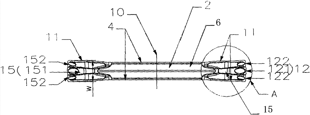
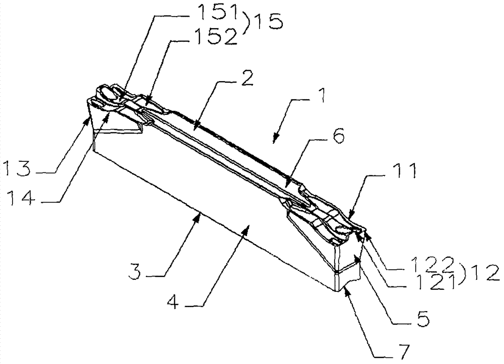
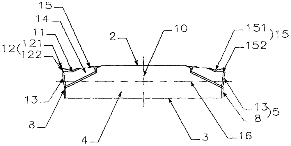
[0032] Figure 1 to Figure 6 An embodiment of the grooving blade of the present invention is shown, the blade 1 is surrounded by an upper positioning surface 2, a lower positioning surface 3, two side surfaces 4 and two end surfaces 5 connecting the upper and lower positioning surfaces, the The upper positioning surface 2 is provided with an upper positioning slope group 6, and the lower positioning surface 3 is provided with a lower positioning slope group 7. In order to facilitate manufacture and installation, the upper positioning slope group 6 and the lower positioning slope group 7 have symmetrical cross-sectional shapes. Between the two end surfaces 5 and the upper positioning surface 2, a rake surface 15 connecting the upper surface 2 and the end surface 5 is respectively provided, and two side flank surfaces 13 are provided between the rake surface 15 and the adjacent end surface 5 and the side surface 4, The two end faces 5 are all composed of an end positioning face ...


PUM


Abstract

The invention discloses a groove machining blade. The groove machining blade is defined by an upper positioning surface, a lower positioning surface, two side surfaces and two end surfaces, wherein the two side surfaces and the two end surfaces connect the upper positioning surface with the lower positioning surface. A front cutter surface connecting the upper surface with at least one of the end surfaces is arranged between the end surface and the upper positioning surface. Two side rear cutter surfaces are arranged between the single front cutter surface and the adjacent end surface as well as between the single front cutter surface and the adjacent side surface correspondingly. The side rear cutter surfaces, the end surfaces and the front cutter surface intersect to form a side edge and an end edge correspondingly. The end edge of a double-edged structure is composed of an upper end edge body and a lower end edge body. The groove machining blade has the characteristics of being high in chip breaking ability, high in machining surface quality, long in life and high in cutting efficiency.

Description

technical field [0001] The invention relates to the field of metal cutting, in particular to a grooving insert with strong chip breaking ability, high processing surface quality and long impact-resistant service life. Background technique [0002] Grooving inserts are mainly used for radial cutting, grooving and end grooving. The end edge is generally a straight edge shape. During processing, the entire end edge is always in contact with the full width of the workpiece. The cutting force is large, the vibration is severe, and the blade is easy to wear When machining large depth-of-cut workpieces, multiple tool changes are required to complete workpiece processing, which greatly reduces cutting efficiency. At the same time, it is difficult to discharge the large-width and hard-to-break chips generated during the processing, which causes severe extrusion and scratching of the chips and the grooved surface, which seriously affects the quality of the processed surface and reduce...

Claims


Application Information

Patent Timeline
Patent Type & Authority Applications(China)
IPC IPC(8): B23B27/00
CPCB23B27/00B23B2200/0485B23B2200/28
Inventor 刘辞海江爱胜刘宏
Owner 刘辞海
Why Eureka
Try Eureka