Cutting tool for cylinder sleeve base body

A cutting device and substrate technology, applied in positioning devices, manufacturing tools, metal processing and other directions, can solve the problems of unguaranteed cutting effect, the degree of automation needs to be improved, and the cutting efficiency is low. The effect of short pause times

Inactive Publication Date: 2017-12-01
ZYNP GRP ANHUI CO LTD
View PDF11 Cites 2 Cited by
  • Summary
  • Abstract
  • Description
  • Claims
  • Application Information

AI Technical Summary

Problems solved by technology

The manual cutting method is labor-intensive, the cutting efficiency is low, and the cutting effect cannot be guaranteed
Although mechanical cutting can achieve high-precision cutting o

Method used


Image

  • Cutting tool for cylinder sleeve base body
  • Cutting tool for cylinder sleeve base body
  • Cutting tool for cylinder sleeve base body

Examples


Embodiment Construction

[0035] The content of the present invention will be described below in conjunction with specific embodiments.

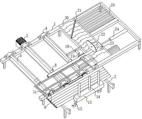
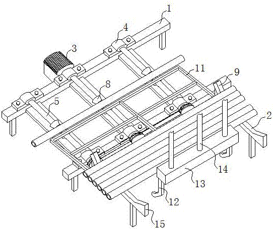
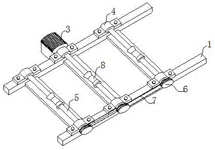
[0036] Such as Figure 1~7 As shown, the cylinder liner matrix cutting device proposed by the present invention includes a feeding device and a cutting device, the feeding device is used to transfer the cylinder liner matrix to the cutting device, and the cutting device is used to cut the cylinder liner matrix .

[0037] The cutting device includes a clamping mechanism, a cutting mechanism and a pushing mechanism.

[0038] The clamping mechanism is located on the discharge side of the feeding device, and the clamping mechanism includes two clamping plates 19 and a first hydraulic cylinder 18 oppositely arranged, and the two clamping plates 19 are respectively located on both sides of the cylinder liner base , the clamping plate 19 is drivingly connected to the movable end of the first hydraulic cylinder 18, and is driven by the first hydraulic cylinder 18 to move f...


PUM


Abstract

The invention discloses a cutting tool for a cylinder sleeve base body. A clamping mechanism is located on the discharging side of a feeding device. The clamping mechanism comprises two oppositely-arranged clamping plates and first hydraulic cylinders, wherein the two clamping plates are located on the two sides of the cylinder sleeve base body correspondingly, and the clamping plates are connected with the movable ends of the first hydraulic cylinders in a driven mode and driven by the first hydraulic cylinders to move front and back. A cutting mechanism is located on the side, backing onto the feeding device, of the clamping mechanism. The cutting mechanism comprises a cutting wheel and a second hydraulic cylinder, wherein the cutting wheel is connected with the movable end of the second hydraulic cylinder in a driven mode and driven by the second hydraulic cylinder to draw close to or get away from the cylinder sleeve base body. A pushing mechanism is located on the side, backing onto the clamping mechanism, of the cutting mechanism. The pushing mechanism comprises a pushing plate and a third hydraulic cylinder, wherein the pushing plate is in the conveying direction of the cylinder sleeve base body, connected with the movable end of the third hydraulic cylinder in a driven mode and driven by the third hydraulic cylinder to move horizontally. According to the cutting tool for the cylinder sleeve base body, manual attendance is not needed in the cutting process, labor intensity is relieved, and the automation degree is improved.

Description

technical field [0001] The invention relates to the field of cylinder liner production, in particular to a cylinder liner matrix cutting tool. Background technique [0002] Automobile engine is a machine that can convert other forms of energy into mechanical energy. It is the heart of the automobile and affects the power, economy and environmental protection of the automobile. As one of the main accessories of the engine, the cylinder liner is a key component of the A-level engine, and its performance directly affects the technical requirements of the engine's power, reliability, economy, emission, and noise. [0003] In the cylinder liner production process, the cast cylinder liner base needs to be cut to length. The traditional cutting methods are nothing more than manual cutting and mechanical cutting. The manual cutting method is labor-intensive, the cutting efficiency is low, and the cutting effect cannot be guaranteed. Although mechanical cutting can achieve high-pre...

Claims


Application Information

Patent Timeline
IPC IPC(8): B23D79/00B23Q3/08B23Q7/06
CPCB23D79/00B23Q3/082B23Q7/06
Inventor 黄德松
Owner ZYNP GRP ANHUI CO LTD
Why Eureka
Try Eureka