
Connecting rod visual auxiliary locating laser groove cutting device and control method

An auxiliary positioning and laser cutting technology, which is applied to laser welding equipment, manufacturing tools, welding equipment, etc., can solve the problems of affecting the machining accuracy of the cracking groove of the big head hole of the connecting rod, and the manual positioning accuracy is not high, so as to simplify the laser cutting positioning procedure, Precise position and controllable processing position deviation

Active Publication Date: 2017-12-01
GUANGDONG UNIV OF TECH
View PDF11 Cites 4 Cited by
  • Summary
  • Abstract
  • Description
  • Claims
  • Application Information

AI Technical Summary

Problems solved by technology

[0006] The main purpose of the present invention is to propose a laser grooving device with simple structure, low cost, high-efficiency operation, mature and reliable, and easy to disassemble and maintain. High, which affects the technical problems of the machining accuracy of the cracking groove of the big head hole of the connecting rod

Method used


Image

  • Connecting rod visual auxiliary locating laser groove cutting device and control method
  • Connecting rod visual auxiliary locating laser groove cutting device and control method

Examples


Embodiment Construction

[0029] The technical solutions in the embodiments of the present invention will be clearly and completely described below in conjunction with the accompanying drawings in the embodiments of the present invention. Obviously, the described embodiments are only a part of the embodiments of the present invention, rather than all the embodiments. Based on the embodiments of the present invention, all other embodiments obtained by those of ordinary skill in the art without creative work shall fall within the protection scope of the present invention.

[0030] It should be noted that if there is a directional indication (such as up, down, left, right, front, back...) in the embodiment of the present invention, the directional indication is only used to explain that it is in a specific posture (as shown in the drawings). If the specific posture changes, the relative positional relationship, movement, etc. of the components below will also change the directional indication accordingly.

[0...


PUM


Abstract

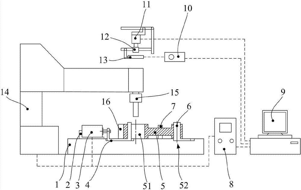
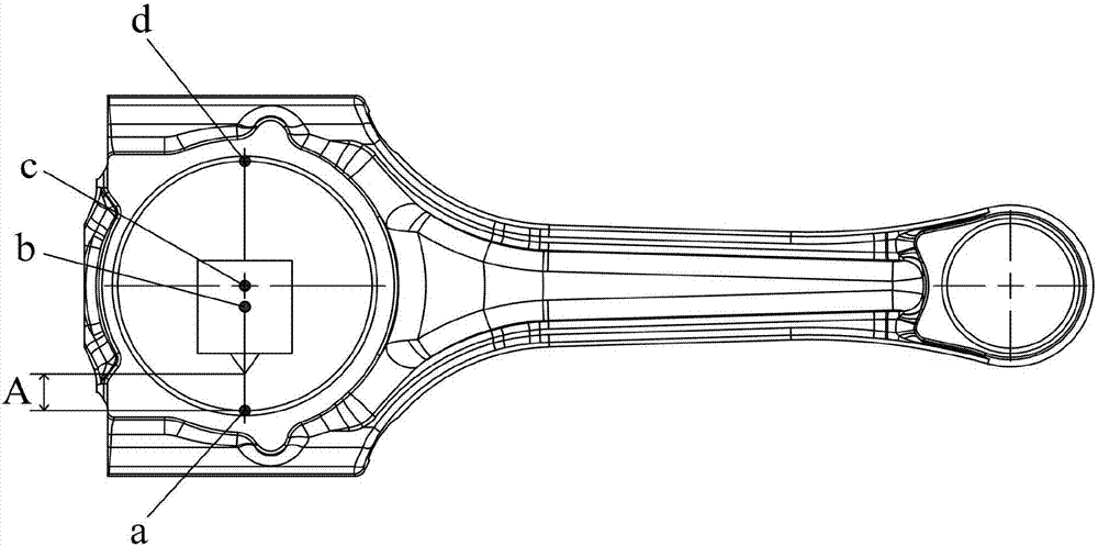
The invention discloses a connecting rod visual auxiliary locating laser groove cutting device which comprises a work platform. A drive cylinder base is fixed to one side of the top face of the work platform. A drive cylinder is fixed to the top face of the drive cylinder base. The power output end of the drive cylinder is connected with a connecting rod large end hole tensioning rod. The other end of the connecting rod large end hole tensioning rod is connected to the inner circumferential face of a connecting rod large end hole in an abutting manner. The top face of the work platform is further connected with a connecting rod small end hole tensioning rod penetrating into a connecting rod small end hole. An industrial camera is arranged above the center of the connecting rod large end hole to be electrically connected with a computer processor. The computer processor is further electrically connected with a laser movement platform through a controller. A laser device is arranged at the top of the laser movement platform and can move to the position above the connecting rod large end hole to carry out connecting rod cracking groove laser cutting on the inner circumferential face of the connecting rod large end hole. The invention further provides a control method of the connecting rod visual auxiliary locating laser groove cutting device. Compared with the prior art, according to the technical scheme, the connecting rod visual auxiliary locating laser groove cutting device has the beneficial effects of being simple in structure, low in cost, efficient in operating, mature, reliable, convenient to demount, mount and maintain and the like.

Description

Technical field [0001] The present invention relates to the technical field of visual assisted positioning, in particular to a laser grooving device and a control method for connecting rod visual assisted positioning. Background technique [0002] Machine vision refers to a special vision system that enables machines to have visual perception functions and uses applications as the research background. Machine vision can provide a description of scenes related to the execution of a specific task. Machine vision can obtain a two-dimensional image of the environment through a vision sensor, and analyze and interpret it through a vision processor, and then convert it into a symbol, so that the robot can recognize the object and obtain the data information of the object, and finally output mechanical operation instructions. Nowadays, machine vision technology has been able to solve the problem of automatic identification in industry. [0003] In the automobile connecting rod cracking g...

Claims


Application Information

Patent Timeline
Patent Type & Authority Applications(China)
IPC IPC(8): B23K26/38B23K26/70
CPCB23K26/38B23K26/702
Inventor 王冠李志鹏关蕾郭钟宁
Owner GUANGDONG UNIV OF TECH
Learn More