Shunting system of sintering smoke circulating loop

A technology of circulation loop and shunt system, applied in the field of iron and steel metallurgy, can solve the problems of uneven flow field, bias flow in the width direction, and difference in the flow of combustion accelerant, and achieve the effects of ensuring production stability, slowing down hedging, and suppressing bias flow.

Pending Publication Date: 2017-12-01
HUATIAN ENG & TECH CORP MCC +1
View PDF11 Cites 2 Cited by
  • Summary
  • Abstract
  • Description
  • Claims
  • Application Information

AI Technical Summary

Problems solved by technology

[0004] However, judging from the existing practical application, there is still a relatively abrupt problem in the sintering flue gas circulation technology, that is, the flow field of the circulating flue gas in the flue gas hood of the sintering machine is seriously uneven
The main reasons for the above problems are: (1) For small and medium-sized sintering machines, a single-side circulation loop is adopted, and the shunt pipe connected to the fume hood of the sintering machine is designed vertically to the fume hood, and the diffusion in the width and length directions of the sintering machine The effect is poor, and it is easy to have bias flow in the width direction; (2) For large-scale sintering machines, double-sided circulation loops are adopted, and the shunt pipe connected to the fume hood of the sintering machine is designed to be inclined, and the circulation on the left and right sides of the fume hood Although the flue gas hedging improves the flow field distribution in the width direction of the sintering machine, the diffusion of the flue gas in the length direction of the sintering machine is still not good
[0005] The problem of uneven flow field in the flue gas hood of the sintering machine can easily cause the difference in the flow rate of the combustion aid in different areas of the sintering machine, especially near the edge of the sintering machine trolley, which in turn affects the difference in sinter quality and metallurgical indicators in different areas

Method used


Image

  • Shunting system of sintering smoke circulating loop
  • Shunting system of sintering smoke circulating loop
  • Shunting system of sintering smoke circulating loop

Examples


Embodiment 1

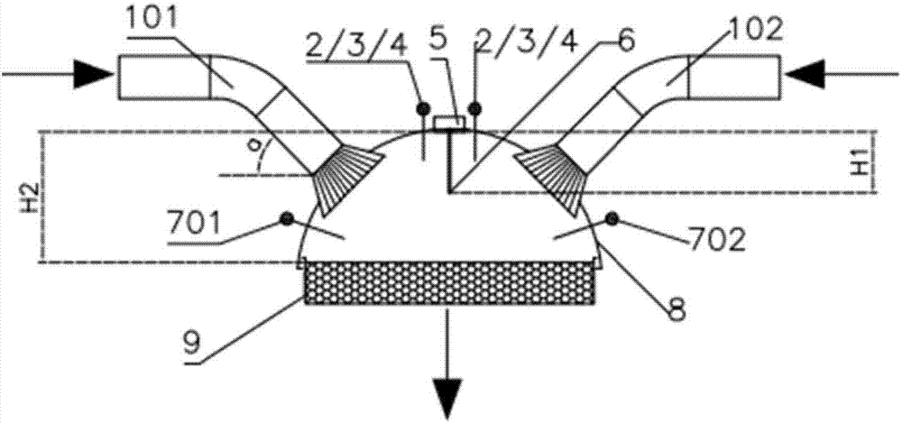
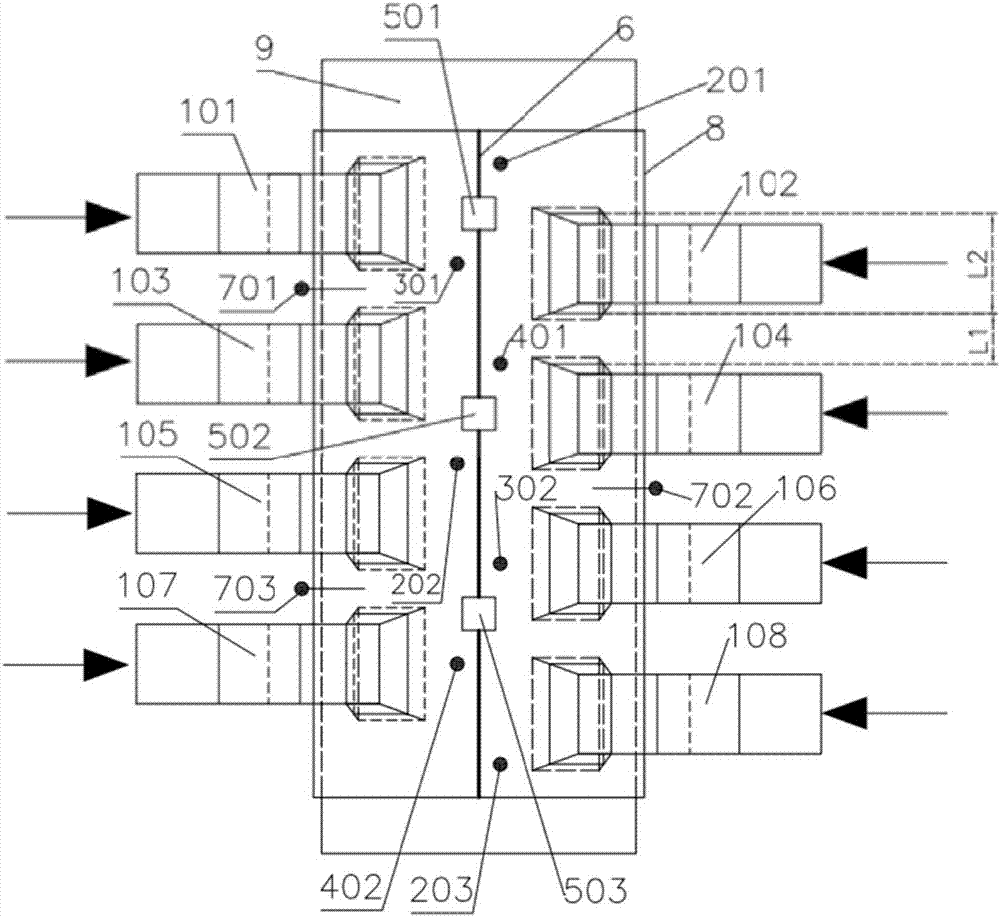
[0029] Such as figure 1 and figure 2 Shown is the distribution system of the sintering flue gas circulation loop of the present invention. After the circulating flue gas from the sintering machine is evenly distributed through the distribution pipes 101-108, it is introduced into the flue gas hood 8 of the sintering machine for cyclic sintering.

[0030] The sintering machine fume hood 8 covers the top of the sintering machine trolley 9, and the flue gas inlets are set at 45° on both sides of the width direction and communicate with the gas outlets of the shunt pipes 101-108; The plate 6 and the baffle plate 6 run through the entire sintering machine fume hood 8 with a height of H1, the distance between the top of the sintering machine fume hood 8 and the sintered material surface is H2, and H1 is 50% of H2.

[0031] The distribution pipes 101-108 on both sides of the fume hood 8 of the sintering machine are equal in number, all of which are 4, and the left and right sides a...

Embodiment 2

[0034] On the basis of the above-mentioned embodiment 1, this embodiment further defines:

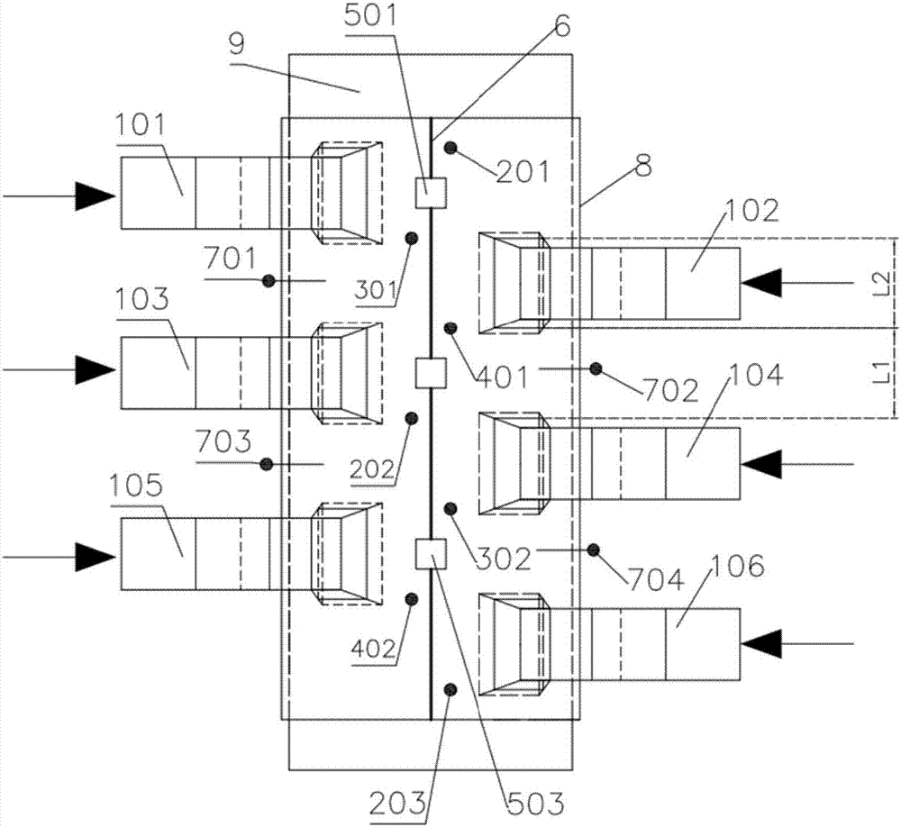
[0035] Such as image 3 As shown, except for the differences in the following structures, the structural layout of the distribution system of this embodiment is the same as that of Embodiment 1: the distribution pipes 101-106 on both sides of the sintering machine fume hood 8 are equal in number, all of which are three, and the left and right sides The side is arranged in a staggered arrangement; along the length direction of the sintering machine trolley 9, the distance between any two shunt pipes 101 / 103 is L1, the width of the shunt pipes 101-106 is L2, and L1 is equal to L2.

Embodiment 3

[0037] On the basis of the above-mentioned embodiment 1 or embodiment 2, this embodiment further defines:

[0038] Such as figure 2 or image 3 As shown, the structural arrangement of the shunt system in this embodiment is different from that in Embodiment 1 or Embodiment 2 in that:

[0039] (1) The angle between the flue gas inlet pipe of the sintering machine flue gas hood 8 and the horizontal direction can fluctuate within the range of 30° to 45°;

[0040] (2) The height of the baffle plate 6 is H1, which is not greater than the distance between the top of the sintering machine fume hood 8 and the sintering material surface is H2, and H1 can fluctuate within the range of 25% to 50% of H2;

[0041] (3) The distance between any two shunt pipes 101 / 103 is L1, the width of shunt pipes 101-108 is L2, and L1 can fluctuate within the range of 50%-100% of L2;

[0042] (4) The inclined pipes of the shunt pipes 101 to 108 connected to the flue gas hood 8 of the sintering machine ...


PUM


Abstract

The invention discloses a shunting system of a sintering smoke circulating loop. The shunting system comprises a smoke cover mounted on a sintering machine trolley; more than two shunting pipes are respectively arranged on two sides of the width direction of the smoke cover; baffle plates are arranged in the smoke cover of a sintering machine in the middle positions of orifices of the shunting pipes on two sides; and the heights of the baffle plates are lower than the distance from the top of the smoke cover of the sintering machine to the surface of a sintered material. Through use of multiple measures, a sintering smoke circulating process achieves the technical purposes of effectively relieving the hedging of circulating smoke on two sides of the width direction of the smoke cover, effectively inhibiting the bias of circulating smoke in the width direction of the sintering machine, effectively accelerating the dispersion of the circulating smoke in different directions in the smoke cover and adjusting the openness of a skylight valve in real time.

Description

technical field [0001] The invention relates to the technical field of iron and steel metallurgy, in particular to a distribution system for a sintering flue gas circulation loop. Background technique [0002] The iron ore sintering process will continue to play a vital role in steel production for a long time. In my country, since October 1, 2012, with the implementation of the "New Standards for Pollutant Discharge in the Iron and Steel Industry", the sintering flue gas circulation process has gradually become an application hotspot in the industry. [0003] Sintering flue gas recycling technology is a sintering method that returns part of the heat-carrying gas discharged during the sintering process to the trolley behind the sintering igniter for reuse. It is essentially another form of hot air sintering technology, and sintering fume can be recovered The waste heat of the gas can be used to improve the heat utilization efficiency of the sintering process and reduce the ...

Claims


Application Information

Patent Timeline
Patent Type & Authority Applications(China)
IPC IPC(8): C22B1/16
CPCC22B1/16
Inventor 王淦王浩余波
Owner HUATIAN ENG & TECH CORP MCC
Why Eureka
Try Eureka