Eureka AIR delivers breakthrough ideas for toughest innovation challenges, trusted by R&D personnel around the world.

High-precision transparent hydro-viscous transmission experimental test device

A test device and transparent liquid technology, applied in the direction of machine gear/transmission mechanism test, material inspection products, etc., can solve the problems of inconvenient operation and detection, unreasonable structure of the experimental device, and inability to observe the oil film between the sheets, etc., to achieve comprehensive measurement parameters , Fast and convenient adjustment, high precision effect

Pending Publication Date: 2017-12-01
苏州方德锐精密机电科技有限公司
View PDF5 Cites 9 Cited by
  • Summary
  • Abstract
  • Description
  • Claims
  • Application Information

AI Technical Summary

Problems solved by technology

At present, there are still deficiencies in the experimental research of hydraulic viscous transmission technology, and the experimental device has shortcomings such as unreasonable structure, inconvenient operation and detection, etc.
In August 2006, Jiang Jianyong of Zhejiang University disclosed a liquid viscous experimental device on pages 18-36 of the book "Development of Liquid Viscous Speed-Governing Clutch Test System" in August 2006. Stepless speed regulation between 0% and 100% of rated speed, but there is no observation hole, so it is impossible to observe the oil film between the plates
In January 2012, Hu Jibin from Beijing Institute of Technology disclosed a single-plate wet clutch test bench in the article "Experimental Research on Drag Torque for Single-plate Wet Clutch". The condition of the oil film between the friction plates, but its output end is fixed, so the thickness of the oil film cannot be adjusted precisely

Method used


Image

  • High-precision transparent hydro-viscous transmission experimental test device
  • High-precision transparent hydro-viscous transmission experimental test device
  • High-precision transparent hydro-viscous transmission experimental test device

Examples


Embodiment Construction

[0014] Below in conjunction with accompanying drawing and specific embodiment the present invention will be further described:

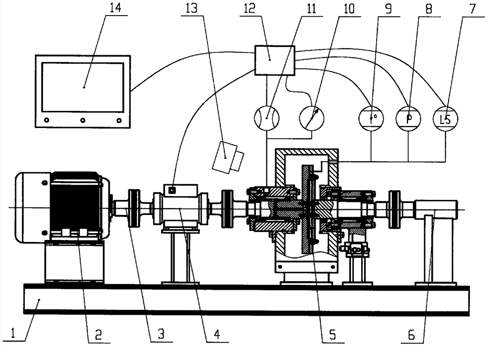
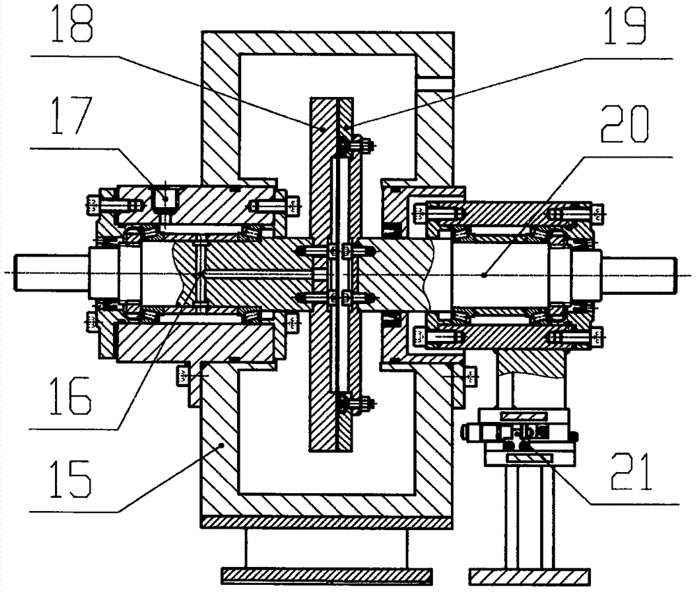
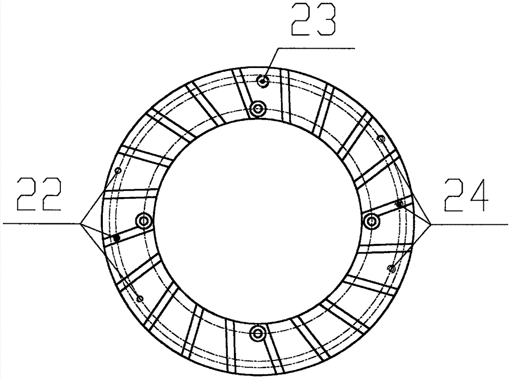
[0015] Such as figure 1 As shown, a high-precision transparent liquid-viscous transmission experimental testing device of the present invention mainly includes a base 1, a motor 2, a shaft coupling 3, a torque tachometer 4, a host 5, a locking device 6, a displacement sensor 7, a pressure Sensor 8, temperature sensor 9, pressure gauge 10, flow meter 11, data acquisition card 12, high-speed camera 13 and computer 14, etc. Such as figure 2 As shown, the main engine 5 mainly includes a transparent box body 15, a driving shaft assembly 16, an oil inlet 17, a transparent active sheet 18, a passive sheet 19, a driven shaft assembly 20, and a distance adjustment assembly 21, etc. Such as image 3 As shown, the passive plate 19 is provided with a temperature sensor mounting hole 22, a displacement sensor mounting hole 23 and a pressure sensor mounting ho...


PUM


Abstract

The invention discloses a high-precision transparent hydro-viscous transmission experimental test device which mainly includes a base, a motor, a coupling, a torque and speed measuring instrument, a host, a locking device, a displacement sensor, a pressure sensor, a temperature sensor, a pressure gauge, a flow meter, a data acquisition card, a high-speed camera, a computer, and the like. The motor, the torque and speed measuring instrument, the host and the locking device are fixed to the base by bolts, and are driven by the coupling. The displacement sensor, the pressure sensor and the temperature sensor are installed on a passive film through threaded connection. The pressure gauge and the flow meter are connected with an oil inlet through a pipeline. The data acquisition card is connected with the detection sensors and the computer, and is used for collecting, processing and outputting signals. The high-speed camera is installed outside a transparent box, and is used for photographing an oil layer between active and passive films. The device has the advantages of fast and convenient adjustment, comprehensive measurement parameters, high test precision, multi-angle observation, and dynamic real-time test.

Description

technical field [0001] The invention relates to an experimental testing device, in particular to a fluid-viscous transmission experimental testing device. Background technique [0002] Hydraulic viscous transmission, also known as oil film shear transmission, is a new type of fluid transmission technology, which mainly uses the oil film shearing effect between the active and passive friction plates to transmit torque, and controls the transmission torque by adjusting the thickness of the oil film, which can It has been widely used in the field of speed regulation and energy saving of high-power fans and water pumps for long-term work under slipping conditions and stepless speed regulation. [0003] While the hydroviscous transmission technology is developing, it is also being continuously improved and updated. It is necessary to conduct theoretical and experimental research on its structure, control and detection systems. At present, there are still deficiencies in the expe...

Claims


Application Information

Patent Timeline
Patent Type & Authority Applications(China)
IPC IPC(8): G01M13/02G01N33/28
CPCG01M13/02G01N33/28
Inventor 谢方伟
Owner 苏州方德锐精密机电科技有限公司
Why Eureka
Eureka Blog
Learn More