
Gas-liquid two-phase flow swirl phase separation type capacitor moisture content measuring device

A gas-liquid two-phase flow, measurement device technology, applied in measurement devices, material capacitance, analysis materials, etc., can solve problems such as difficulty in measuring phase holdup, dependence on capacitance sensor response, and difficulty in improving system spatial resolution, and achieve stability. Effective flow pattern adjustment, simple structure effect

Inactive Publication Date: 2017-12-01
TIANJIN UNIV
View PDF10 Cites 11 Cited by
  • Summary
  • Abstract
  • Description
  • Claims
  • Application Information

AI Technical Summary

Problems solved by technology

Electrical capacitance tomography is widely used to visualize the flow morphological phase distribution measurement, but the theoretical soft field problem has not yet been solved, and the system has great difficulties in improving the spatial resolution
In addition, researchers at home and abroad have carried out a lot of work on the measurement of phase holdup in multiphase flow, and have accumulated valuable experience in optimizing the capacitor structure and its excitation mode. However, when faced with the measurement of phase holdup, scholars We all realize the importance of the flow form, but affected by many factors, the two-phase flow presents the characteristics of complexity and randomness, and the response of the capacitive sensor is still strongly dependent on the spatial distribution of the phase medium, which brings great pressure to the measurement of the phase holdup. It's very difficult

Method used


Image

  • Gas-liquid two-phase flow swirl phase separation type capacitor moisture content measuring device
  • Gas-liquid two-phase flow swirl phase separation type capacitor moisture content measuring device
  • Gas-liquid two-phase flow swirl phase separation type capacitor moisture content measuring device

Examples


Embodiment Construction

[0023] The present invention will be described in further detail below with reference to the accompanying drawings.

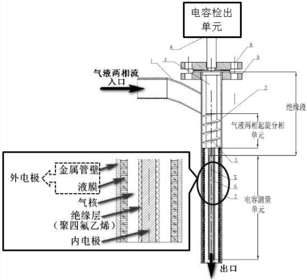
[0024] The present invention is a water content measuring device used in the gas-liquid two-phase flow measurement, the structural diagram is as follows figure 1 shown. The principle of the gas-liquid two-phase flow measurement device is not limited, it can be a flow measurement sensor of any principle, such as various standard and non-standard throttling devices such as cone, Venturi, nozzle and orifice, and can also be used with ultrasonic, Flow meters with different principles such as mass and thermal are used together.

[0025] Such as figure 1 shown. The device of the present invention is installed on a gas-liquid two-phase flow pipeline. The fluid passes through the inlet pipeline 1 and flows into the spinning phase-separation unit 2 tangentially. Natural flow guide without resistance, the spiral blade 3 is firmly connected with the support body 4 of ...


PUM


Abstract

The invention belongs to the technical field of gas-liquid two-phase measurement and relates to a gas-liquid two-phase flow swirl phase separation type capacitor moisture content measuring device. The device comprises a swirl phase separation unit and a capacitor measuring unit, wherein the swirl phase separation unit is located on the upper part of the device and comprises an outer pipe wall and spiral blades fixed in the outer pipe wall, and a space between the spiral blades and the outer pipe wall is named a first phase medium flow space; the capacitor measuring unit is located on the lower part of the device and comprises a metal pipe wall and an inner electrode, the metal pipe wall is taken as an outer electrode, the inner electrode is fixed in the metal pipe wall and externally covered with an insulating layer, a space between the metal pipe wall and the insulating layer is named a second phase medium flow space, and the two phase medium flow spaces are communicated with each other; and an opening connected with a fluid tangential inlet pipeline is formed in the outer pipe wall, the tangential angle of the fluid tangential inlet pipeline is the same as the spiral rising angles of the spiral blades, and therefore, fluid can enter the swirl phase separation unit along the tangential angle.

Description

technical field [0001] The invention belongs to the technical field of gas-liquid two-phase flow measurement, and relates to a measuring device for measuring water content. Background technique [0002] Gas-liquid two-phase flow exists widely in nature and industrial processes, such as petroleum, chemical industry, metallurgy, nuclear energy, aerospace and other fields. In recent decades, people have put forward higher and higher requirements for liquid cut-up measurement in gas-liquid two-phase flow. However, the existing research results show that due to the complexity of the gas-liquid two-phase flow flow pattern diversity, it is still difficult to accurately measure the gas-liquid two-phase flow, especially the water content when the liquid phase is water. with great difficulty. At present, the commonly used means of water content are separator-based technology, tracer technology, ray technology and capacitive technology. Separator-based measurement technology has the...

Claims


Application Information

Patent Timeline
Patent Type & Authority Applications(China)
IPC IPC(8): G01N27/22
CPCG01N27/223
Inventor 张涛徐英
Owner TIANJIN UNIV
Learn More