
Diagnosis method for diagnosing sampling resistance drift

A technology of sampling resistance and diagnosis method, which is applied in the field of digital instrument control, can solve problems such as exceeding the standard and cannot identify the accuracy of the acquisition channel, and achieve the effect of wide application prospect, predictability and normal operation.

Inactive Publication Date: 2017-12-01
CHINA NUCLEAR CONTROL SYST ENG
View PDF4 Cites 3 Cited by
  • Summary
  • Abstract
  • Description
  • Claims
  • Application Information

AI Technical Summary

Problems solved by technology

[0004] The purpose of the present invention is to provide a diagnostic method for sampling resistance drift, which is used to solve the problem in the prior art that the AI ​​module cannot identify whether the accuracy of the acquisition channel exceeds the standard due to resistance drift

Method used


Image

  • Diagnosis method for diagnosing sampling resistance drift
  • Diagnosis method for diagnosing sampling resistance drift

Examples


Embodiment 1

[0030] (1) Obtain the diagnostic reference voltage U hx and the full circuit voltage U x

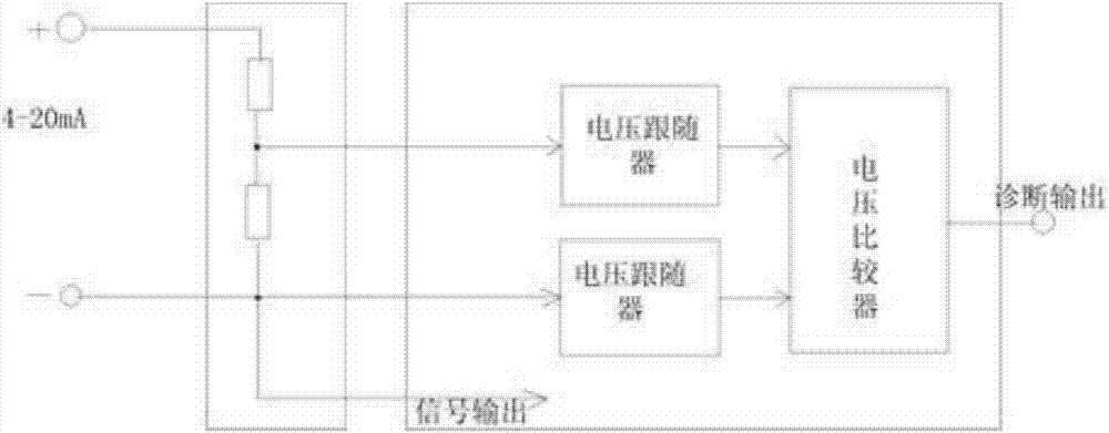
[0031] Build a sampling circuit: the sampling circuit includes a power supply and a sampling resistor, the sampling resistor includes a first sampling resistor and a second sampling resistor, and the first sampling resistor and the second sampling resistor are equal in value.

[0032] (2) Perform threshold comparison between the obtained diagnostic reference voltage Uhx of the sampling resistor and the full voltage output signal Ux of the sampling circuit to obtain a compared result;

[0033] The sampling circuit is composed of two high-precision resistors with equal resistance in series, U hx The voltage developed for one of the resistors, the full circuit voltage, U x for the voltage drop across the two resistors. Due to factors such as discrete device parameters and signal differences in the actual circuit, the voltage value is not doubled. The actual corresponding relationship sh...

Embodiment 2

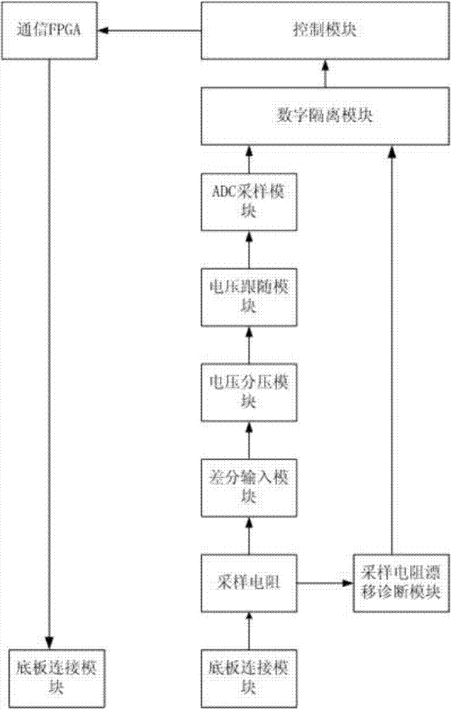
[0049] Such as figure 2 As shown, a nuclear power plant safety-level digital control system based on the sampling resistor drift diagnosis system is used for nuclear power plant safety level, including the base plate connection module, sampling resistor, differential input module, voltage divider module, voltage following module, sampling Resistance drift diagnosis module, digital isolation module, ADC sampling module, control module, communication FPGA;

[0050] The backplane connection module is used to transmit the analog signal to the sampling resistor,

[0051] The sampling resistor is used to transmit the analog signal to the differential input module, and also transmits the analog signal to the sampling resistor drift diagnosis module for processing, and the sampling resistor drift diagnosis module transmits the processed diagnosis result to the digital isolation module;

[0052] The differential input module transmits the analog signal to the voltage divider module, ...


PUM


Abstract

The invention discloses a diagnosis method for diagnosing the sampling resistance drift, a diagnosis system and a digital control system. The diagnosis method comprises the following steps of (1) constructing sampling circuits Uhx and Ux, and acquiring the sampling circuits; (2) carrying out threshold comparison on the Uhx and the Ux to obtain compared output signals; (3) based on the output signals, acquiring the diagnosis result of the sampling resistance drift. The diagnosis system comprises a sampling module and a diagnosis module. The sampling module is used for acquiring a Uhx signal and a Ux, and transmitting the Uhx signal and the Ux to the diagnosis module respectively. The diagnosis module is used for comparing the Uhx signal with the Ux, and obtaining an output signal according to the comparison result. According to the invention, the sampling resistance drift faults of analog input can be diagnosed. Therefore, the predictability of signal input and the reliability of a verification and acquisition channel circuit are guaranteed. The method is novel, unique, practical and applicable.

Description

technical field [0001] The invention belongs to the field of digital instrument control, and relates to a diagnostic method for sampling resistance drift in nuclear power plants, industrial sites and other analog signal collections. Background technique [0002] There are a large number of analog quantity acquisition modules in digital instrument control systems of nuclear power plants and industrial sites. The physical parameters (such as temperature, pressure, flow, etc.) System and the upper computer of the operating system, so as to realize real-time monitoring, recording, decision-making and control of the operating status of the system or equipment. The acquisition accuracy of the AI ​​module directly affects the correctness and timeliness of the decision-making and control of the instrument control system of the nuclear power plant, and the key indicator that affects the sampling accuracy of the AI ​​module is the stability of its sampling resistor. [0003] The thr...

Claims


Application Information

Patent Timeline
IPC IPC(8): G01R27/02
CPCG01R27/02
Inventor 刘明星童强马权吴志强刘艳阳曾少立王远兵周静梁建李建辉
Owner CHINA NUCLEAR CONTROL SYST ENG
Learn More