Method for generating Airy beam with any initial emission angle

A technology of Airy beams and emission angles, applied in the field of transformation and regulation, beam transmission

Inactive Publication Date: 2017-12-01
ZHEJIANG NORMAL UNIVERSITY
View PDF3 Cites 2 Cited by
  • Summary
  • Abstract
  • Description
  • Claims
  • Application Information

AI Technical Summary

Problems solved by technology

Obviously, it is impossible for a phase mask of finite size to generate an Airy beam with an arbitrarily large initial emission angle

Method used


Image

  • Method for generating Airy beam with any initial emission angle
  • Method for generating Airy beam with any initial emission angle

Examples


Embodiment Construction

[0015] The present invention will be further described below in conjunction with the accompanying drawings and embodiments.

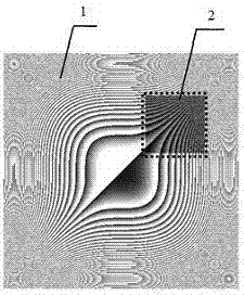
[0016] figure 1 The dotted line in the middle is a schematic diagram (2) of selecting a local area from the theoretical cubic phase diagram (1), and using the selected local area to make figure 2 Phase mask (6) in .

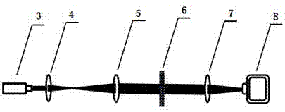
[0017] figure 2 Produce the schematic diagram of the Airy beam experiment device with any initial emission angle for the present invention, the experiment device includes: laser beam (3), beam expander collimation system (4,5), phase mask plate (6), Fourier transform Lens (7), scientific CCD camera (8).

[0018] The experiment implementation process is as follows:

[0019] 1. Select different regions (2) from the theoretical cubic phase diagram (1), and process the phase mask (6). That is, the amplitude of the horizontal and vertical misalignment between the center of the phase plate and the optical axis is changed, thereby changing...


PUM


Abstract

The invention discloses a method for generating an Airy beam with an initial emission angle. On the basis of the diffraction theory and the definition of the Airy function, an Airy beam is generated through deviating the center of an Airy beam cubic phase plate from the optical axis of a Fourier transforming lens, and the deviating distance can be used for changing the transmission track of the Airy beam. The larger the deviating distance, the larger the initial emission angle of the Airy beam. Based on the above principle, a theoretically calculated local area of a cubic phase diagram, deviating from the center, is selected to manufacture a phase mask plate. An incident light beam irradiates the local phase mask plate to generate an Airy beam with an initial emission angle. Phase mask plates manufactured for different areas of the phase diagram can be used for generating Airy beams with different initial emission angles. According to the invention, the local area of the phase diagram is used for manufacturing the phase mask plate. Therefore, the problems in the prior art that a traditional phase modulation element is limited in size, the initial emission angle of the Airy beam is limited in regulation and control range, and a large-size phase modulation element is too high in manufacturing cost can be solved effectively.

Description

technical field [0001] The invention relates to a light beam transmission, conversion and regulation technology, and discloses a method for generating Airy light beams with arbitrary initial emission angles. Past studies have shown that the center of the theoretical cubic phase diagram deviates from the optical axis of the Fourier transform lens, which can control the transmission trajectory of the Airy accelerated beam. The initial emission angle of the Airy beam is determined according to the position away from the center of the cubic phase diagram, and a local area of ​​the theoretical cubic phase diagram can be selected to make a cubic phase mask to generate an Airy beam with an initial emission angle to realize control of the Airy beam. The purpose of the beam delivery trajectory. Background technique [0002] The Airy beam is a new type of non-diffracting beam. Its biggest feature is that it can accelerate laterally during the propagation process, similar to the acce...

Claims


Application Information

Patent Timeline
Patent Type & Authority Applications(China)
IPC IPC(8): G02B27/09
CPCG02B27/0938
Inventor 任志君
Owner ZHEJIANG NORMAL UNIVERSITY
Why Eureka
Try Eureka