Waterproof structure of dry-type transformer

A technology of dry-type transformers and transformers, which is applied in transformer/inductor components, transformer/inductor shells, transformer/inductor cooling, etc., and can solve problems such as single structure, unfavorable heat, and imperfect considerations, etc., to achieve increased Large shading range, increased heat dissipation efficiency, and guaranteed connectivity

Active Publication Date: 2017-12-01
ZHEJIANG DONGRUI ENERGY SAVING TECH
View PDF7 Cites 0 Cited by
  • Summary
  • Abstract
  • Description
  • Claims
  • Application Information

AI Technical Summary

Problems solved by technology

[0003] At present, the waterproof mechanism of dry-type transformers widely used in us has a single structure. Generally, it is only a protective shell to isolate moisture. However, this design is not conducive to the loss of heat generated by work, which will affect the transformer. The working efficiency of some waterproof mechanisms is only considered in the design of the top of the water or the flow of atmospheric precipitation, the consideration is not very perfect, resulting in the waterproof effect is not very good

Method used


Image

  • Waterproof structure of dry-type transformer
  • Waterproof structure of dry-type transformer
  • Waterproof structure of dry-type transformer

Examples


Embodiment

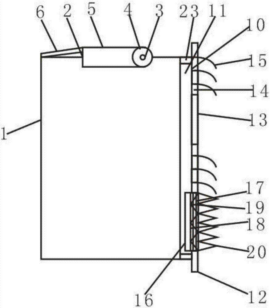
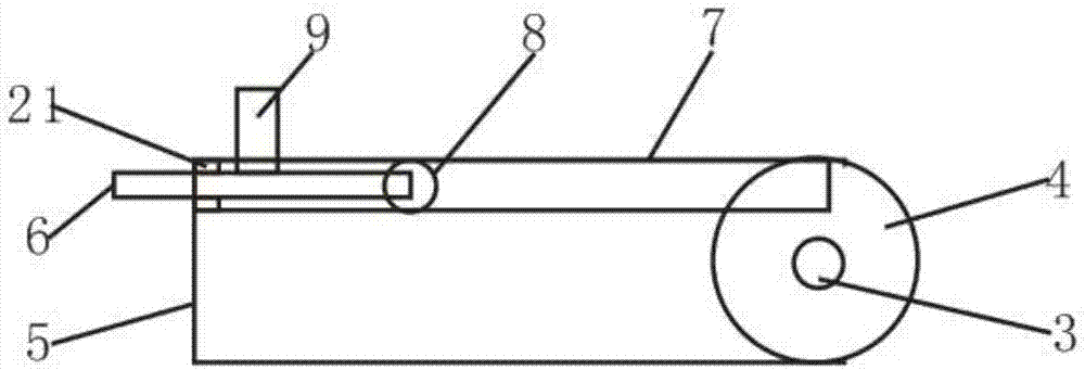
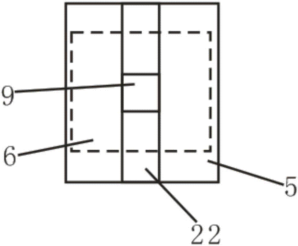
[0020] like figure 1 , figure 2 and image 3 As shown, the present invention provides a waterproof mechanism for dry-type transformers, including a transformer outer box 1, the top of the transformer outer box 1 is provided with a top heat dissipation hole 2, the top heat dissipation hole 2 increases heat dissipation efficiency, and the top heat dissipation hole 2 A rotating shaft 3 is connected inside, and a rotating ring 4 is arranged on the outside of the rotating shaft 3. A shroud 5 is connected to the outer side of the rotating ring 4. The shroud 5 is used to shield the top during the heat dissipation process. The shroud 5 and the top The heat dissipation holes 2 are all rectangular in shape, and the areas of the two rectangles are equal. The inside of the shutter 5 is provided with an expansion plate 6 and an expansion slot 7. The expansion plate 6 is located inside the expansion slot 7, and the expansion slot The end of 7 is provided with a shielding ring 21, the int...


PUM


Abstract

The invention discloses a waterproof structure of a dry-type transformer. The waterproof structure comprises a transformer outer tank, wherein a top cooling hole is formed in the top of the transformer outer tank; the inside of the top cooling hole is connected with a rotating shaft; a rotating ring is arranged at the outer side of the rotating shaft; the outer side of the rotating ring is connected with a shutter; an expansion board and an expansion slot are arranged in the shutter; a waterproof cover is arranged at the outer side of the transformer outer tank and comprises an inner plate and an outer plate; the inner plate is arranged in the transformer outer tank; side cooling holes are formed in the surface of the outer plate; the outer sides of the side cooling holes are connected with waterproof sheets; a buffer groove is formed in the bottom end of the outer plate; the inside of the buffer groove is connected with a support plate; a sleeve plate is arranged at the outer side of the support plate; a spring is arranged in the sleeve plate; and the outer side of the sleeve plate is connected with a two-way baffle plate. The heat dissipation efficiency is improved through the top cooling hole and the side cooling holes; top shielding is increased through the expansion board; a sealing gasket is used for preventing water from entering through the edge of the inner plate; the waterproof sheets are capable of preventing rainwater from flowing into the device; and the two-way baffle plate is used for draining top rainwater and also is capable of preventing bottom running water from flowing into the side cooling holes.

Description

technical field [0001] The invention relates to the technical field of waterproof mechanisms, in particular to a waterproof mechanism for dry-type transformers. Background technique [0002] Dry-type transformers are widely used in local lighting, high-rise buildings, airports, wharf CNC mechanical equipment and other places. Simply put, dry-type transformers refer to transformers whose iron core and windings are not immersed in insulating oil. The cooling method is divided into natural air cooling ( AN) and forced air cooling (AF), when natural air cooling, the transformer can run continuously at the rated capacity for a long time, when forced air cooling, the output capacity of the transformer can be increased by 50%, suitable for intermittent overload operation, or emergency accident overload Operation; due to the large increase in load loss and impedance voltage during overload, it is in a non-economic operating state, so it should not be in continuous overload operation...

Claims


Application Information

Patent Timeline
Patent Type & Authority Applications(China)
IPC IPC(8): H01F27/02H01F27/08H02B1/28
CPCH01F27/02H01F27/025H01F27/085H02B1/28
Inventor 陈波
Owner ZHEJIANG DONGRUI ENERGY SAVING TECH
Why Eureka
Try Eureka