High speed permanent magnetism motor rotor and high speed permanent magnetism motor

A permanent magnet motor, high-speed technology, applied in the direction of magnetic circuit rotating parts, magnetic circuits, electric components, etc., can solve the problems of large eddy current loss, poor heat dissipation, low rigidity, etc., to solve the problem of large eddy current loss and reduce production process. , the effect of improving production efficiency

Pending Publication Date: 2017-12-01
NEW UNITED RAIL TRANSIT TECH
View PDF6 Cites 6 Cited by
  • Summary
  • Abstract
  • Description
  • Claims
  • Application Information

AI Technical Summary

Problems solved by technology

[0007] The purpose of the present invention is to provide a high-speed permanent magnet motor rotor, which can improve production eff

Method used


Image

  • High speed permanent magnetism motor rotor and high speed permanent magnetism motor
  • High speed permanent magnetism motor rotor and high speed permanent magnetism motor
  • High speed permanent magnetism motor rotor and high speed permanent magnetism motor

Examples


Embodiment 1

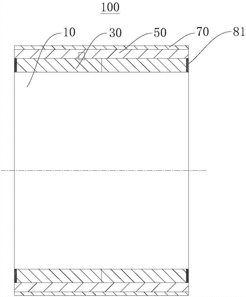
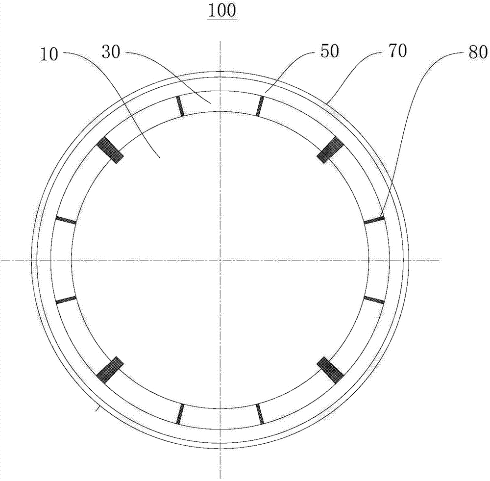
[0043] Please refer to figure 1 and figure 2 , this embodiment provides a high-speed permanent magnet motor rotor 100, including:

[0044] Rotor core 10;

[0045] The number of magnetic steel 30 is multiple, and the multiple magnetic steel 30 is arranged on the outer surface of the rotor core 10 in segments along the axial direction and the circumferential direction of the rotor core 10;

[0046] The shielding layer 50 is wrapped on the outer surface of the magnetic steel 30 and has an interference fit with the magnetic steel 30;

[0047] The outer protective sheath 70 is wrapped around the outer surface of the shielding layer 50; and

[0048] The sealing part is used to fill the interpole gap of the magnetic steel 30 and seal the end faces of the magnetic steel 30 at both ends of the entire high-speed permanent magnet motor rotor 100 .

[0049] Wherein, the magnetic steel 30 is arranged on the outer surface of the rotor core 10 by pasting.

[0050] Wherein, the thicknes...

Embodiment 2

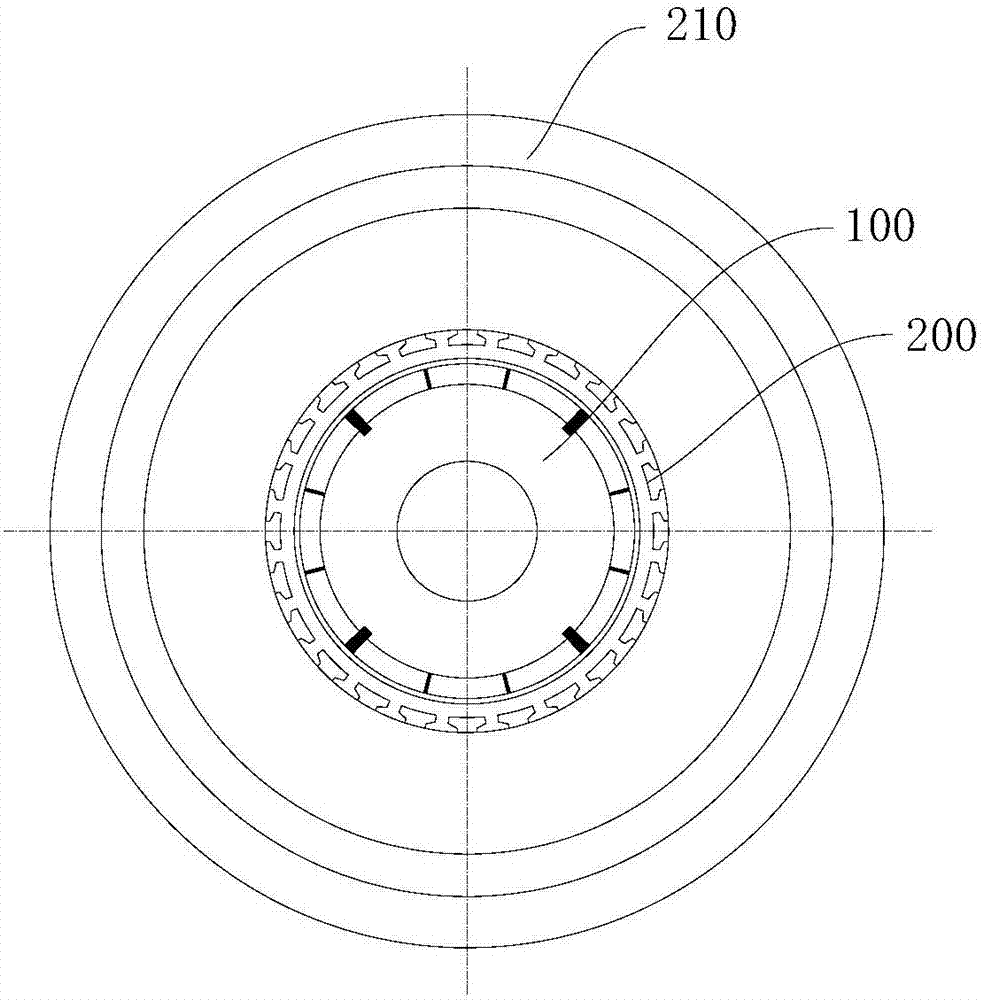
[0068] Please refer to image 3 and Figure 4 This embodiment provides a high-speed permanent magnet motor, including a stator core 200 and the high-speed permanent magnet motor rotor 100 in Embodiment 1. The high-speed permanent magnet motor rotor 100 is installed in the space enclosed by the stator core 200 .

[0069] Further, the high-speed permanent magnet motor also includes a water jacket 210 for cooling, and the water jacket 210 is set outside the stator core 200 . Specifically, a shrink-fit connection can be used.

[0070] There is a heat exchange channel 2101 in the water jacket 210, through which the flow of cooling fluid in the heat exchange channel 2101 can accelerate the heat dissipation of the high-speed permanent magnet motor to avoid excessive temperature.

[0071] There are sealing ring installation grooves on both sides of the water jacket 210, and the sealing rings installed in the grooves can prevent the cooling fluid in the heat exchange channel 2101 fro...


PUM

PropertyMeasurementUnit
Thicknessaaaaaaaaaa
Thicknessaaaaaaaaaa
Thicknessaaaaaaaaaa

Abstract

The invention provides a high speed permanent magnetism motor rotor and a high speed permanent magnetism motor, and relates to the motor making technical field; the high speed permanent magnetism motor rotor comprises the following units: a rotor iron core; a plurality of magnetic steels arranged in peripheral sections on the outer surface of the rotor iron core along the rotor iron core axis direction; a shielding layer wrapping the magnetic steel outer surface and in interference fit with the magnetic steels; a protection cover sheath wrapping the shielding layer outer surface; a sealing portion used for filling the magnetic steel inter-electrode gaps and sealing end faces of the magnetic steels on two ends of the whole high speed permanent magnetism motor rotor; the high speed permanent magnetism motor comprises a stator iron core and the high speed permanent magnetism motor rotor; the high speed permanent magnetism motor rotor is arranged in a space enclosed by the stator iron core; the high speed permanent magnetism motor rotor and the high speed permanent magnetism motor can solve the problems that a conventional motor rotor is large in eddy current loss, high in temperature rise, poor in heat radiation capability and low in rigidity; the high speed permanent magnetism motor and the high speed permanent magnetism motor rotor can be more conveniently manufactured with high efficiency, thus better adapting to the present usage demands.

Description

technical field [0001] The invention relates to the technical field of motor manufacturing, in particular to a high-speed permanent magnet motor rotor and a high-speed permanent magnet motor. Background technique [0002] High-speed motors usually refer to motors with a speed exceeding 10000r / min. Generally speaking, the familiar squirrel cage rotor asynchronous motors, solid rotor asynchronous motors, wire wound rotor synchronous motors, permanent magnet motors, induction motors, switched reluctance Motors, etc. can be used in high-speed occasions. [0003] Among them, the high-speed permanent magnet motor has the advantages of high efficiency and high power density, and has great application potential. [0004] Today, when high-speed permanent magnet motors are more and more widely used, there are such problems: [0005] As an important part of the high-speed permanent magnet motor, the motor rotor has a cumbersome and time-consuming processing technology, which is not c...

Claims


Application Information

Patent Timeline
IPC IPC(8): H02K1/27H02K11/01
CPCH02K1/2706H02K11/01
Inventor 孙丽娟
Owner NEW UNITED RAIL TRANSIT TECH
Why Eureka
Try Eureka