
Source plate applied to photovoltaic plate

A technology of photoelectric boards and connecting boards, which is applied to parts of color TVs, parts of TV systems, TVs, etc., can solve the problems of increasing product costs, high assembly costs, and high costs, reducing the probability of board warping and reducing The total cost of the product and the effect of mitigating mechanical vibration

Inactive Publication Date: 2017-12-01
HUIZHOU GAOSHENGDA TECH CO LTD
View PDF0 Cites 0 Cited by
  • Summary
  • Abstract
  • Description
  • Claims
  • Application Information

AI Technical Summary

Problems solved by technology

[0003] 1. The management is cumbersome. It is necessary to import and manage the left and right of the Source board separately, which wastes time and manpower
[0004] 2. The cost of materials, packaging process and transportation is high. Both the left side of the Source board and the right side of the Source board need to be imported and manufactured separately. The loss rate of the PCB substrate is high and it takes man-hours
Occupy more production capacity and more transportation space
In addition, packaging requires two types of trays and two types of molds, which is more expensive
[0005] 3. The risk of product delivery is high. Importing and manufacturing separately requires careful control of each board, which affects production efficiency and further affects product delivery
[0006] 4. The follow-up assembly cost of the Source board is relatively high, and it needs to be imported and manufactured separately. The left side of the Source board and the right side of the Source board need to be installed separately, which increases the difficulty and time of assembly, and reduces the production efficiency of the Source board.
This is a single-point grounding, which is likely to cause instability and poor shielding effectiveness
[0008] As mentioned above, the traditional LCD TV Source board is managed separately, which greatly increases the product cost and reduces the market competitiveness of similar products

Method used


Image

  • Source plate applied to photovoltaic plate
  • Source plate applied to photovoltaic plate
  • Source plate applied to photovoltaic plate

Examples


Embodiment

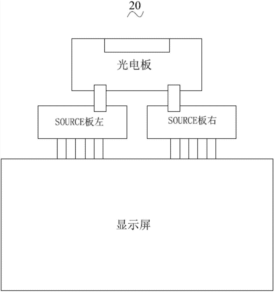
[0034] see figure 1 20 is the connection structure of the Source board of a traditional LCD TV. The left side of the Source board and the right side of the Source board are respectively connected to the photoelectric board, and the left side of the Source board and the right side of the Source board are also connected to the display screen respectively. As a result, each Source board is managed separately, which wastes time and manpower. The left side of the Source board and the Source board need to be installed separately, which increases the difficulty, time and energy of assembly. Each of the left and right panels of Source is individually printed, punched, and assembled, which is not only cumbersome, but also time-consuming, labor-intensive and costly.

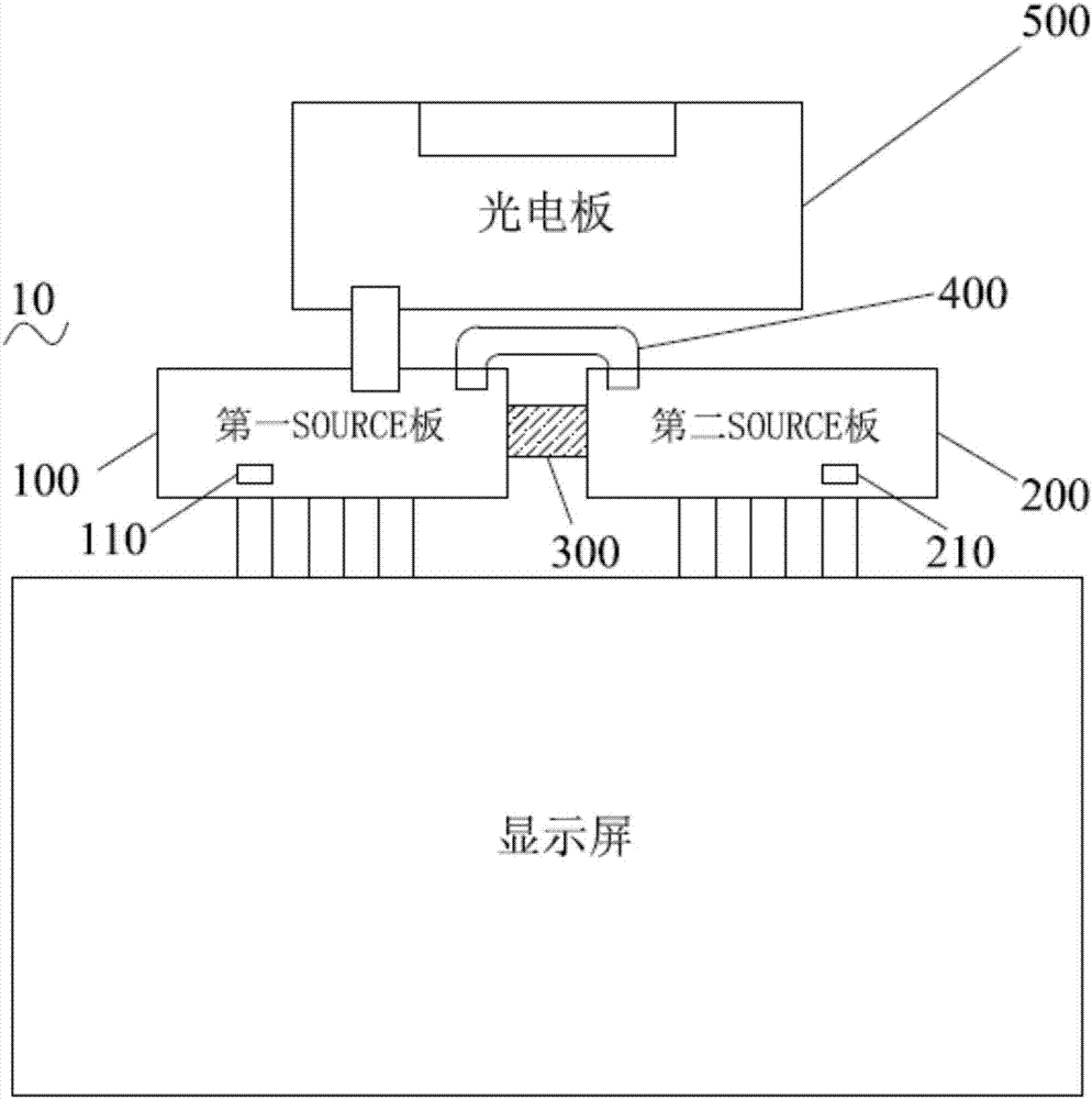
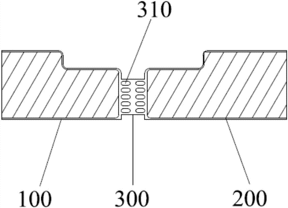
[0035] Based on the shortcomings of the above products, the Source board of the present invention is designed. see figure 2 , providing a Source board applied to photovoltaic panels, including: a Source board body 10, a...


PUM


Abstract

The invention discloses a Source board applied to a photoelectric board, comprising: a Source board body, a connection wire and a connection board, the Source board body includes a first Source board and a second Source board, and the first Source board passes through the connection board The second Source board is fixedly connected, and the first Source board is signal-connected to the second Source board through the connection line; the Source board body is also signal-connected to the photoelectric board. The present invention is a Source board applied to photoelectric boards. The first Source board and the second Source board are connected through a connecting board, so that the two Source boards are combined into one, and can be imported, managed, produced, transported and assembled simultaneously. In turn, it saves production capacity, reduces power consumption during working hours, reduces delivery risks, improves efficiency, and reduces the total cost of products.

Description

technical field [0001] The invention relates to the field of source boards, in particular to a source board applied to photoelectric boards. Background technique [0002] LCD TV is one of the must-haves for home furnishing, and the market competition is relatively fierce. With the advancement of technology and the improvement of user experience, there are higher requirements for LCD TVs. see figure 1 , is the connection structure diagram of the Source board of a traditional LCD TV. The left side of the Source board and the right side of the Source board are respectively connected to the T-con board through the connection board. Therefore, the traditional Source board mainly has the following problems: [0003] 1. The management is cumbersome. It is necessary to import and manage the left and right of the Source board separately, which wastes time and manpower. [0004] 2. The cost of materials, packaging process and transportation is high. Both the left side of the source...

Claims


Application Information

Patent Timeline
Patent Type & Authority Applications(China)
IPC IPC(8): H04N5/64H04N5/44
CPCH04N5/64H04N5/44
Inventor 李亚尹龙珍罗章孙燕陈宇科
Owner HUIZHOU GAOSHENGDA TECH CO LTD
Learn More