Supercharge Your Innovation With Domain-Expert AI Agents!

Disc Rotor- And Axial Flux-Type Rotating Electric Machine

A technology of axial magnetic flux and rotating motors, applied to synchronous motors with stationary armatures and rotating magnets, magnetic circuits, electromechanical devices, etc., can solve problems such as high production costs, achieve simple structure, low moment of inertia, Effect of Torque Increase

Inactive Publication Date: 2017-12-01
奥拉夫伯特舍尔
View PDF10 Cites 0 Cited by
  • Summary
  • Abstract
  • Description
  • Claims
  • Application Information

AI Technical Summary

Problems solved by technology

[0004] Both solutions present relatively complex winding structures and thus involve high production costs

Method used


Image

  • Disc Rotor- And Axial Flux-Type Rotating Electric Machine
  • Disc Rotor- And Axial Flux-Type Rotating Electric Machine
  • Disc Rotor- And Axial Flux-Type Rotating Electric Machine

Examples


Embodiment Construction

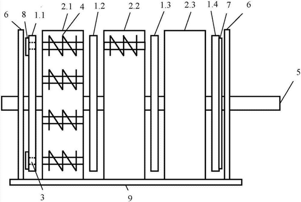
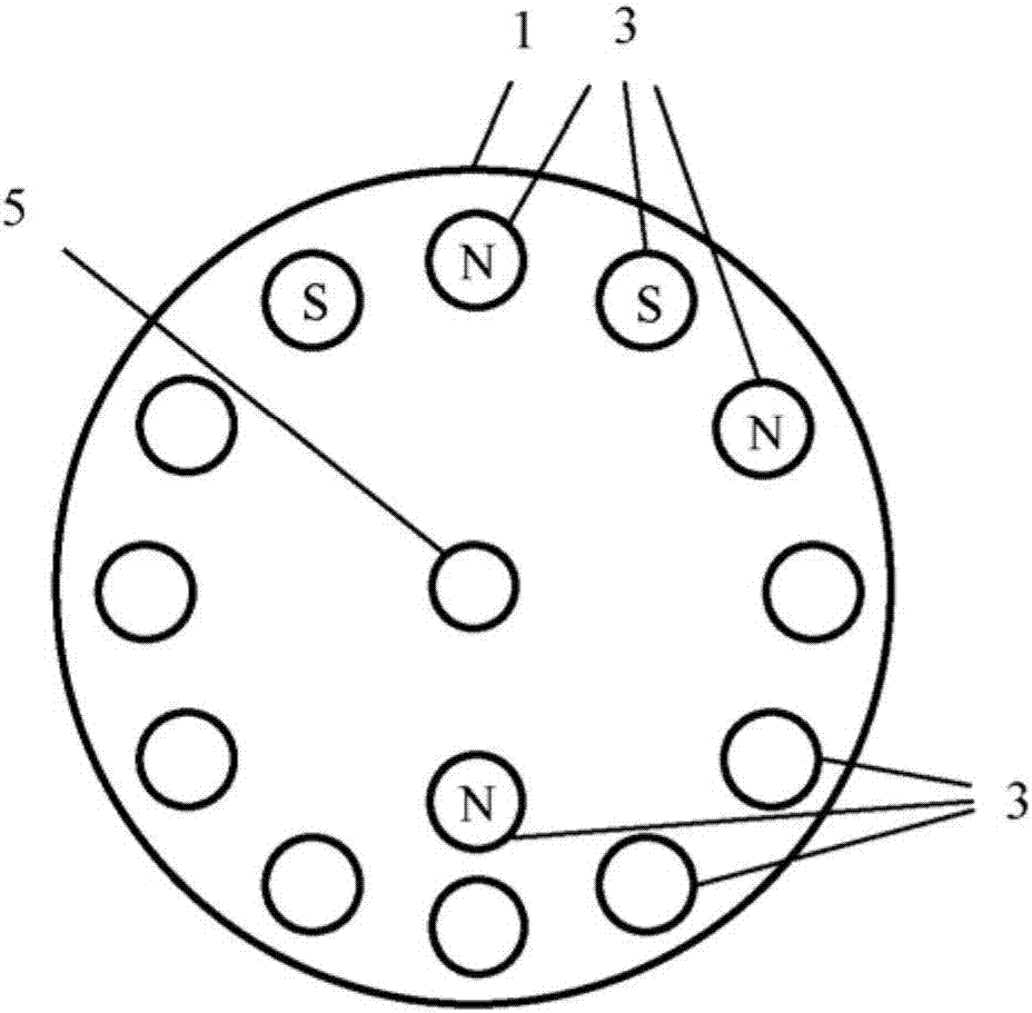
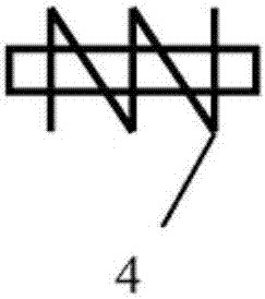
[0021] figure 1 An electric machine according to the invention is shown with three stators 2.1 to 2.3 and four rotors 1.1 to 1.4. The stators 2.1 to 2.3 have in any case twelve coils 4 (see also attached Figure 4 ) and the rotors 1.1 to 1.4 have in any case 16 permanent magnets 3 . In this example, the permanent magnets are arranged in a continuous manner in the rotors 1.1 to 1.4, ie the permanent magnets 3 end flush with the surface of the rotors 1.1 to 1.4. The coils 4 and the permanent magnets 3 are located in each case respectively on annular paths in the rotors 1.1 to 1.4 and in the stators 2.1 to 2.3 and correspond to each other. The shaft 5 is mounted in the stators 2.1 to 2.3. It is also possible that the shaft 5 is mounted in the leftmost and rightmost stator disks 6 . The stators 2.1 to 2.3 are fastened to the base plate 9. The coil 4 is wound on a cylindrical core, preferably of ferrite material. The cross-section of the core and the ends of the core can devi...


PUM


Abstract

The aim of the invention is to provide a simple winding structure on the stator of an axial flux machine and to simultaneously minimize the otherwise normal use of material by means of additional structural measures. The disc rotor- and axial flux-type rotating electric machine consists of at least of two disc-shaped rotors (1) equipped with permanent magnets. A stator (2) with axially arranged coils (4) is located between the rotors (1), and the coils (4) correspond to the permanent magnets (3) of the rotors (1). A shaft (5) is mounted on the stator (2), and the shaft (5) can additionally be mounted on stator discs (6) lying outside of the rotors (1). The rotors are secured to the shaft (5), and the stator (2) or the stator discs (6) are secured to a base or a housing (9).

Description

technical field [0001] A rotating electric machine having a disk rotor and an axial flux type structure has a rotor equipped with permanent magnets. Background technique [0002] A large number of disk rotor machines and axial flux machines are known. The following documents are cited as the closest prior art. Document DE 10322474 A1 describes an electric machine of axial flux type construction with a stator and a rotor positioned relative to each other across an axial air gap. In order to manufacture inexpensively a structurally space-saving axial flux type motor which exhibits a high torque density, the stator has a pole disc with a number of flat pole segments corresponding to the required number of poles, these flat The pole segments are equidistant, distributed in a fan-shaped manner over the disk surface and consist of a magnetically permeable material, and the stator has an annular field winding which, together with the side yokes, is assigned to the pole disks. Of...

Claims


Application Information

Patent Timeline
IPC IPC(8): H02K21/24
CPCH02K21/24H02K1/2798H02K1/2796H02K1/2753H02K3/46H02K7/003H02K1/14H02K1/182H02K3/18H02K3/28H02K16/00
Inventor 奥拉夫·伯特舍尔
Owner 奥拉夫伯特舍尔
Features
  • R&D
  • Intellectual Property
  • Life Sciences
  • Materials
  • Tech Scout
  • Unparalleled Data Quality
  • Higher Quality Content
  • 60% Fewer Hallucinations
Learn More