

Hot-rolled flying shear head and tail initial shearing position dynamic control method
A starting position and dynamic control technology, applied in the direction of tail end control, metal rolling, metal rolling, etc., can solve the problems of flying shear starting shear point control deviation, etc., to reduce the head and tail shear loss, improve Position tracking accuracy and the effect of improving the yield
Active Publication Date: 2017-12-05
BAOSHAN IRON & STEEL CO LTD
View PDF9 Cites 10 Cited by
- Summary
- Abstract
- Description
- Claims
- Application Information
AI Technical Summary
Problems solved by technology
This technical solution is only to calibrate the initial clearance of the flying shear blade, and has no technical inspiration for solving the problem of the control deviation of the initial shear point of the flying shear caused by the deviation of the head and tail tracking position of the strip steel
Method used
View moreImage
Smart ImageViewing Examples

Examples
Embodiment
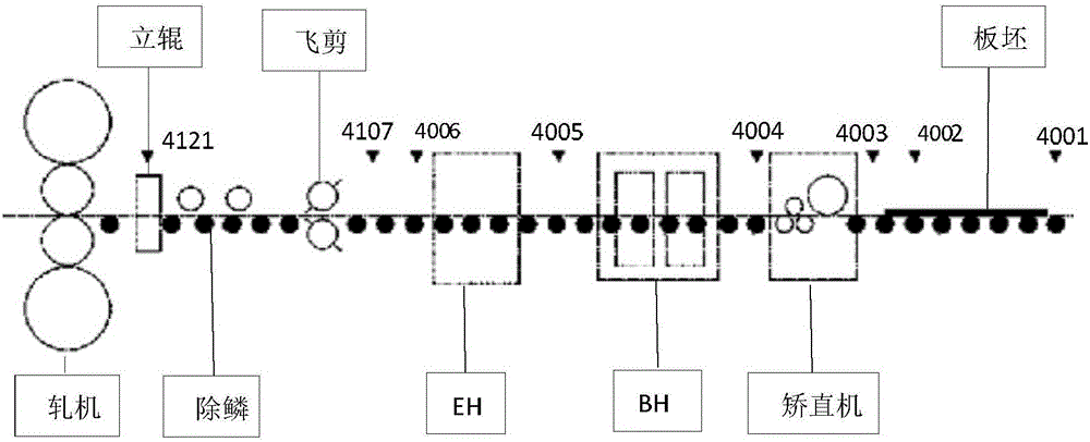
[0057] Step S10: Determine the position detection range between HMD4002-4306;
[0058] Step S20: select HMD4005 as the dynamic detection point;
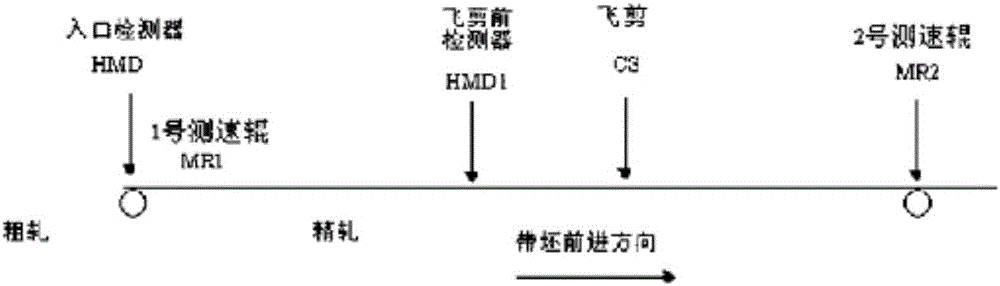
[0059] Step S30: In this embodiment, the distance from the dynamic detection point HMD4005 to the flying shears starting point HMD4107 is 13.3m;
Login to View More PUM
 Abstract
The invention relates to control over a steel billet flying shear of a hot rolling machine, in particular to an initial shearing position dynamic control method applicable to a hot rolling machine flying shear. The method comprises the following steps of determining a position tracking detection range; determining dynamic detection points; calculating the distance from each dynamic detection point to a flying shear start point; determining the width of a tracking travel window; determining the practical running position of a strip steel; determining the calculated shearing length of the strip steel; comparing the calculated shearing length of the strip steel with a strip steel shearing length set value; and starting the flying shear to shear the strip steel. The detection areas of the head and tail positions of the strip steel are controlled through a finish rolling inlet of a hot continuous rolling production line; through combination with arrangement of the strip steel head and tail position tracking travel window and correction of the basic displacement of the strip steel, position tracking integrated initial points are switched dynamically, and dynamic control over strip steel initial shearing position control points is realized. Position tracking data are more aligned with the requirement for the practical site location precision.
Description
technical field [0001] The invention relates to the control of the flying shears of the steel billets of the hot rolling mill, in particular to a method specially suitable for the control of the initial shearing position of the flying shears of the hot rolling mills. Background technique [0002] In the hot rolling production process, there are irregular shapes at the head and tail of the intermediate billet after the steel billet is rolled by the rough rolling mill. Therefore, the irregular parts of the head and tail of the strip must be cut before rolling by the hot tandem rolling mill. When the amount of shear is too small, the shape of the head and tail of the strip will be poor, causing the strip to enter the rolling mill, causing uneven contact between the roll and the surface of the strip, and affecting rolling stability; The billet is cut off, resulting in cutting waste and reducing the finished product rate. [0003] In the actual shearing process, the determinatio...
Claims
Login to View More Application Information
Patent Timeline
 Patent Type & AuthorityApplications(China)
IPC IPC(8): B21B37/72B21B15/00
CPCB21B15/0007B21B37/72B21B2015/0014
Inventor荣鸿伟郁华军周兴泽
OwnerBAOSHAN IRON & STEEL CO LTD