Mine mobile object tracking and location method
A technology of moving target and positioning method, which is applied in the field of mine moving target tracking and positioning, and coal mine underground positioning. It can solve the problems of real-time influence, video data transmission, large processing capacity, and undetectable target, so as to improve real-time performance and accuracy. Accurate, reduce system power consumption, increase the effect of coverage
- Summary
- Abstract
- Description
- Claims
- Application Information
AI Technical Summary
Problems solved by technology
Method used
Image

Examples
Embodiment Construction
[0041] The present invention will be described in detail below in conjunction with the accompanying drawings and specific embodiments.
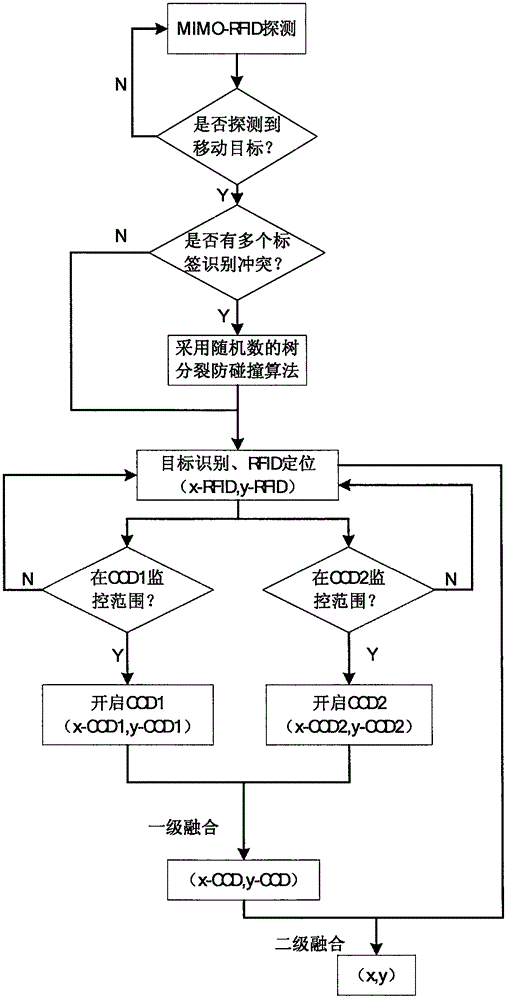
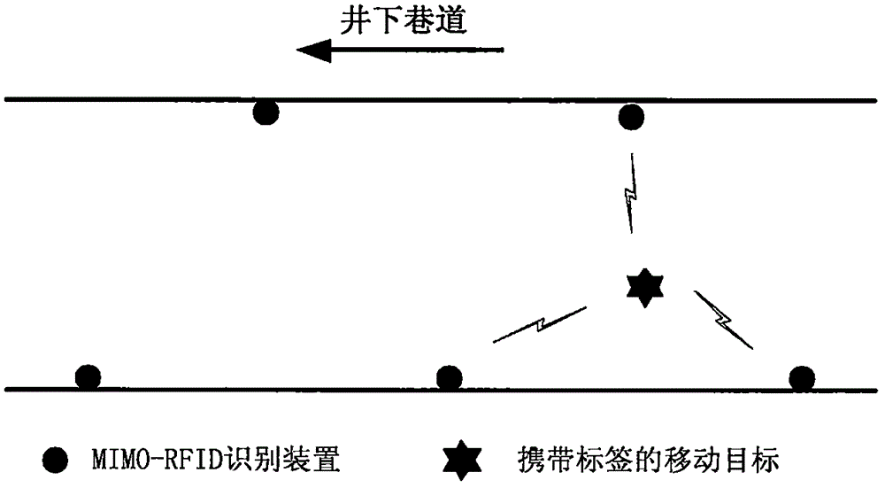
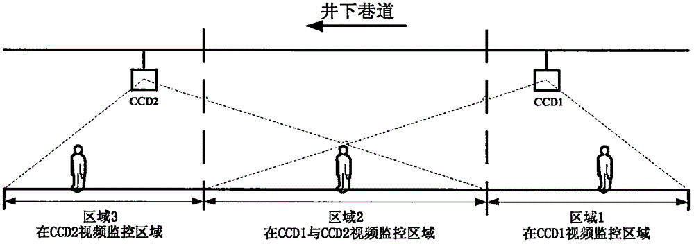
[0042] refer to figure 1 , is the flow chart of mine moving target tracking and positioning. First, use the multi-antenna radio frequency identification device to identify the target and obtain its current position coordinate information, and then use this information to guide the image sensor to turn on or sleep, and use the background difference method to detect the target in the video surveillance image and perform multi-view fusion to achieve more accurate positioning , and finally through the weighted fusion algorithm to fuse the two positioning results to obtain the location information of the moving target. The image sensor has an antenna module and a wireless interface function, and is used to receive communication instructions from the multi-antenna radio frequency identification device. The specific implementation steps are as fol...
PUM
 Abstract
Description
Claims
Application Information