Wind turbine rotor blade

A technology of rotor blades and wind energy equipment, which is applied to the wake of rotor blades and the field of rotor blades of wind energy equipment, and can solve the problems of wind energy equipment output power loss, large wake, etc.

Inactive Publication Date: 2017-12-05
WOBBEN PROPERTIES GMBH
View PDF15 Cites 3 Cited by
  • Summary
  • Abstract
  • Description
  • Claims
  • Application Information

AI Technical Summary

Problems solved by technology

Precisely with the flatback airfoils described above or with an approximately circular cross section, as is used in some cases in the region of the rotor hub, large wakes and correspondingly also wind energy installations occur The large output power loss of the

Method used


Image

  • Wind turbine rotor blade
  • Wind turbine rotor blade
  • Wind turbine rotor blade

Examples


Embodiment Construction

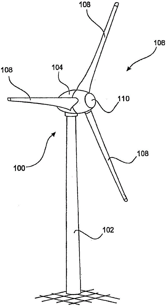
[0037] figure 1 A wind energy installation 100 is shown with a tower 102 and a nacelle 104 . A rotor 106 with three rotor blades 108 and a spinner 110 is arranged on the nacelle 104 . In operation, the rotor 106 is brought into rotational motion by the wind to drive a generator in the nacelle 104 .

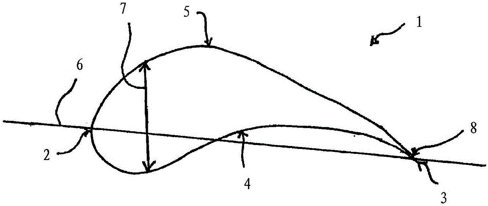
[0038] figure 2 A cross-section through an airfoil 1 of a rotor blade of a wind energy installation according to the prior art is shown. This cross section here has a leading edge 2 and a trailing edge 3 . The lower side 4 and the upper side 5 meet each other at the trailing edge 3 . The trailing edge 3 tapers and flattens here. The trailing edge thickness 8 , ie the thickness of the airfoil 1 at the trailing edge 3 , is here approximately zero. The greatest airfoil thickness 7 of the airfoil 1 is arranged here towards the leading edge 2 . In addition, in figure 2 A chord 6 is shown in , which runs from the leading edge 2 towards the trailing edge 3 .
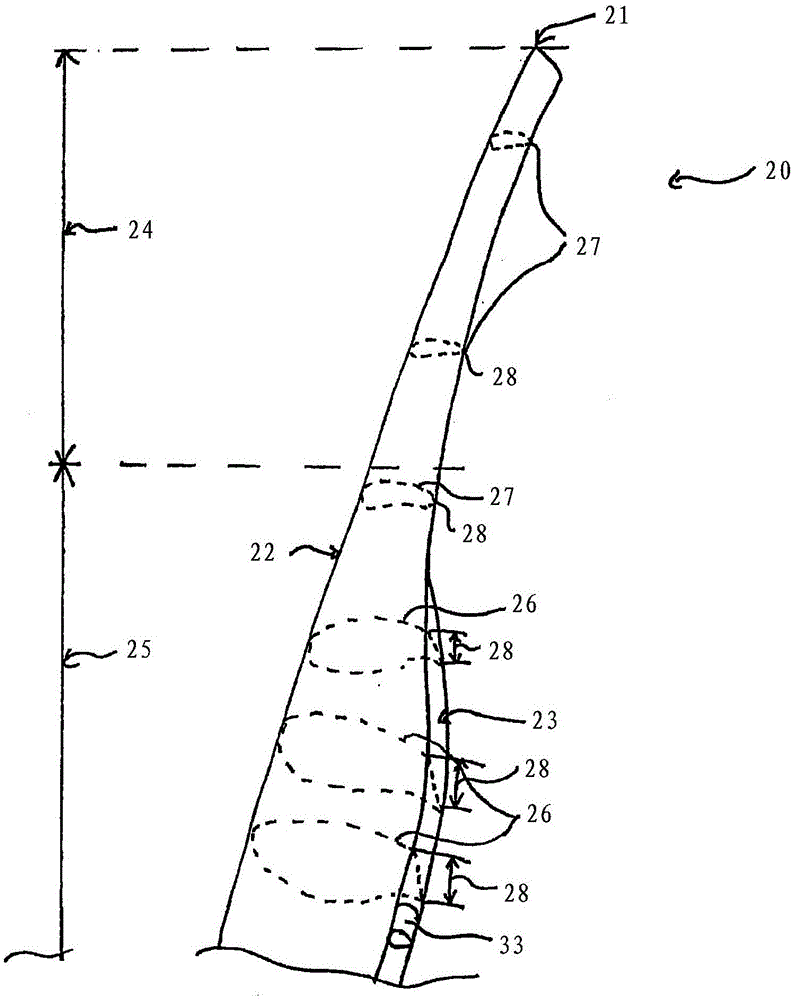
[0039] image 3...


PUM


Abstract

The invention relates to a rotor blade (20, 108, 200) of a wind turbine (100), comprising an inner segment (25, 250), in which the rotor blade (20, 108, 200) is fastened to a rotor hub, and an outer segment (24, 240), which is connected to the rotor blade (20, 108, 200) and has a rotor blade tip (21). The rotor blade (20, 108, 200) in the inner segment (25, 250) has, at least partially, a flatback profile (26, 66, 46, 460) having a truncated rear edge (23, 63, 630), and at least one control unit (33, 53, 54, 79, 81) for controlling the trailing flow at the rotor blade (20, 108, 200) is provided on the flatback profile (26, 66, 46, 460).

Description

technical field [0001] The invention relates to a rotor blade of a wind energy installation and to a wind energy installation. Furthermore, the invention relates to a method for controlling a wake of a rotor blade of a wind energy installation. Background technique [0002] Wind energy installations for generating electricity are generally known and are available, for example, in figure 1 designed as in. In this case, the absorption of mechanical power by the rotor from the wind depends in particular on the design of the rotor blades. Through the increased power absorption, the efficiency of the wind energy installation and thus the output power of the wind energy installation is increased. A common measure for further increasing the power output of a wind energy installation consists in increasing the rotor diameter. As the rotor diameter increases, the profile depth of the rotor blades in the region of the hub generally also increases. In the case of large rotor diame...

Claims


Application Information

Patent Timeline
Patent Type & Authority Applications(China)
IPC IPC(8): F03D1/06
CPCF03D1/06F03D1/0601Y02E10/72B64C23/08F03D1/0641
Inventor 拉尔夫·梅辛哈罗·哈姆斯亨德里克·詹森安德烈·阿尔特米库斯
Owner WOBBEN PROPERTIES GMBH
Why Eureka
Try Eureka