

Efficient cleaning device used for mechanical casting mould
A cleaning device and mechanical casting technology, which is applied in the field of mechanical casting, can solve problems such as protrusions or pits on the surface of products, reducing the mold release rate of finished products, and affecting the quality of molded products, so as to achieve easy operation, convenient and ingenious use , the effect of simple structure
- Summary
- Abstract
- Description
- Claims
- Application Information
AI Technical Summary
Problems solved by technology
Method used
Image

Examples
Embodiment Construction
[0016] The following will clearly and completely describe the technical solutions in the embodiments of the present invention with reference to the accompanying drawings in the embodiments of the present invention. Obviously, the described embodiments are only some, not all, embodiments of the present invention.
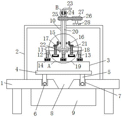
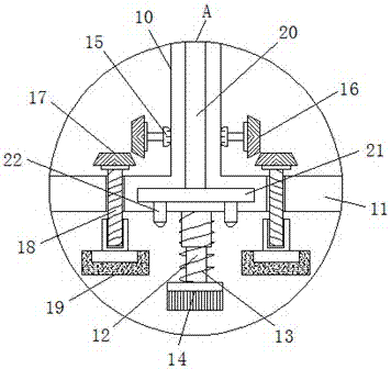
[0017] refer to Figure 1-3 , a high-efficiency cleaning device for mechanical casting moulds, including a workbench 1, the upper end of the workbench 1 is fixedly connected to the organic shell 2, the body shell 2 is provided with a fixed frame 4, and the upper end of the fixed frame 4 is placed on the mold 3, The lower end of the fixed frame 4 is fixedly connected with a supporting column 5 around, and the bottom of the supporting column 5 is provided with a ball 6, and the upper center of the body shell 2 is vertically inserted with a rotating shaft 10, and the lower end of the rotating shaft 10 is horizontally fixedly connected with a Cross bar 11, the lower end ...
PUM
 Abstract
Description
Claims
Application Information