Labeling mechanical hand based on PCB robot production line

A PCB board and robot technology, applied in the field of automation equipment, can solve the problems of high labor intensity, large changes in fixtures, labeling speed, and insufficient labeling flexibility and reliability, reducing equipment investment and floor space, improving Stability and reliability, firm and reliable label application

Active Publication Date: 2017-12-08
FOSHAN NANHAI GUANGDONG TECH UNIV CNC EQUIP COOP INNOVATION INST +1
View PDF5 Cites 5 Cited by
  • Summary
  • Abstract
  • Description
  • Claims
  • Application Information

AI Technical Summary

Problems solved by technology

However, the related parts manufacturing technology and complete machine assembly technology (such as mobile phone shell, glass, cover plate, etc.) have quite mature technology and equipment, high repetition of processing content, high labor intensity, and conform to the characteristics of automation transformation. 3C industry Automation upgrading and transformation will be the blue ocean of intelligent transformation
[0003] Disadvantages of the existing production line: 1) If the positioning of the sheet is not accurate, the product defect rate is high; 2) The production line produces a single product, and the change of the production line tooling and fixture changes greatly and the cycle is long; 3) It is impossible to break through a single station to complete different types of labels Automatic labeling
However, because the existing PCB production line process is completed by a single-suction head labeling machine, there are deficiencies in terms of labeling speed, labeling flexibility, and labeling reliability, and it also increases the cost of the PCB production line.

Method used


Image

  • Labeling mechanical hand based on PCB robot production line
  • Labeling mechanical hand based on PCB robot production line
  • Labeling mechanical hand based on PCB robot production line

Examples


Embodiment 1

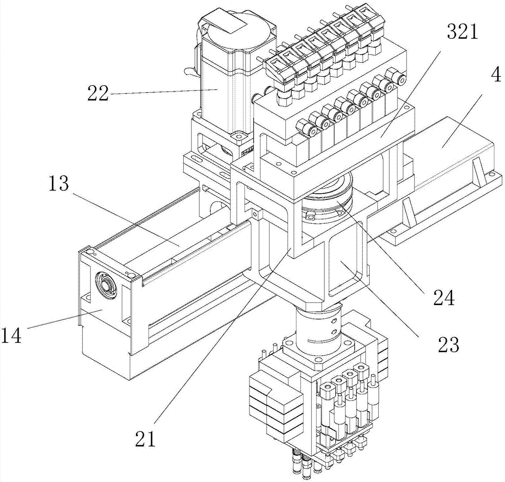
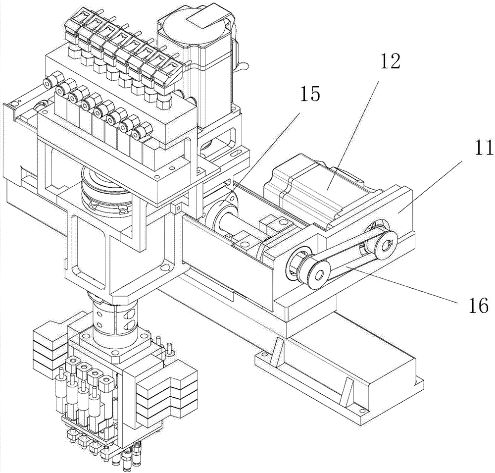
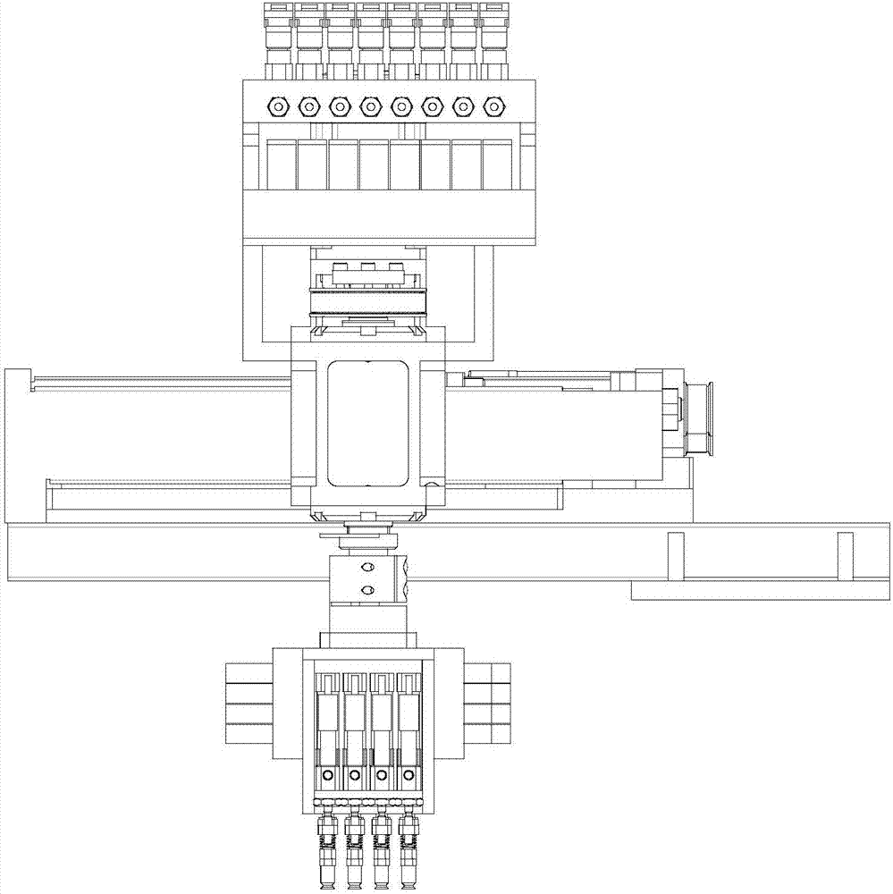
[0040] like figure 1 , figure 2 , image 3 , Figure 4 , Figure 5 and Image 6 As shown, the present invention discloses a labeling manipulator based on a PCB robot production line. The labeling manipulator mainly includes a base 4, a first driving device installed on the base 4, a second driving device installed on the first driving device, And the third driving device installed on the second driving device. The first driving device takes the second driving device to reciprocate linearly between the stripping area and the labeling area, and the second driving device takes the third driving device to the labeling area and then rotates at a certain angle according to the process requirements Labeling.

[0041] Specifically, the first drive device includes a motor mounting base 11, a first motor 12, a first screw 13, a screw seat 14, a first nut 15, and a first screw connecting the first motor 12 and the first screw 13. A timing belt 16. The motor mounting base 11 is f...


PUM


Abstract

The invention discloses a labeling mechanical hand based on a PCB robot production line. The labeling mechanical hand comprises a base, a first drive device, a second drive device and a third drive device mounted on the second drive device. According to the labeling mechanical hand provided by the invention, the first drive device drives a first lead screw to rotate through a first motor, so that the second drive device is driven to move back and forth; the second drive device drives the third drive device to rotate by 360 degrees, so that labeling process requirements of different angles are met; an air cylinder solid valve group drives a pressure head air cylinder group to act, so that a guide rod moves downwards; when a sucking disc stops moving downwards after being in contact with a PCB, a connecting plate continuously pushes a buffer spring to compress downwards as a result of working stroke of the pressure head air cylinder group, so that a label is compacted and is firmly adhered on the PCB, and therefore, the label is prevented from being in hard contact with the PCB to damage precise circuit boards or components and parts, and the good protection effect is achieved. The labeling mechanical hand further has the advantages of being simple in structure, low in manufacturing cost, and stable in reliable in operation.

Description

technical field [0001] The invention relates to the field of automation equipment, in particular to a labeling manipulator based on a PCB board (circuit board) robot production line. Background technique [0002] In recent years, with the continuous development of the domestic economy, labor costs have risen accordingly, and my country's manufacturing manpower advantage is no longer there. Under the background of manufacturing upgrading, "machine substitution" to improve the intelligence of manufacturing industry has become a new trend. At present, the automation rate of my country's 3C industry is still low, and there is still a huge demand for automation transformation. 3C products consist of a large number of components (for example, a mobile phone includes touch screen, display panel, main board PCB, battery, middle board, back cover and other large components, as well as other small components such as camera and structural components), and they are basically non-standar...

Claims


Application Information

Patent Timeline
Patent Type & Authority Applications(China)
IPC IPC(8): B25J11/00B25J19/00B65C9/08B65C9/26
CPCB65C9/08B65C9/26B25J11/00B25J19/00Y02P90/02
Inventor 郑思静
Owner FOSHAN NANHAI GUANGDONG TECH UNIV CNC EQUIP COOP INNOVATION INST
Why Eureka
Try Eureka