
A lifting mechanism, hot melt adhesive label station trolley and combined labeling machine

A technology of lifting mechanism and glue label station, which is applied in the field of lifting mechanism and combined labeling machine, and can solve the problems of low practicability, complicated operation and high cost

Active Publication Date: 2020-10-23
广州市万世德智能装备科技有限公司
View PDF1 Cites 0 Cited by
  • Summary
  • Abstract
  • Description
  • Claims
  • Application Information

AI Technical Summary

Problems solved by technology

[0002] At present, in the bottled beverage industry, the demand for labels is becoming more and more diverse. Conventional labeling machines can only label one type of label. If you want to label other types of labels or combined labeling, you need Multiple devices to run, high cost and low production efficiency
[0003] Before the labeling station performs labeling operations, the height of each working part on the labeling station must be matched. The patent number is CN201010213017.7, and the Chinese invention patent named "Self-adhesive Integral Labeling Station" discloses a lifting mechanism. Self-adhesive overall labeling station, but its lifting mechanism needs to be individually adjusted for each lifting column, the operation is complicated, and the practicability is not high
In the conventional lifting device, the rotation of the screw rod drives the lifting substrate threadedly connected with the screw rod to move up and down, so the screw rod must protrude from the top of the lifting substrate, hindering the placement of parts on the lifting substrate, and there is a certain safety risk

Method used


Image

  • A lifting mechanism, hot melt adhesive label station trolley and combined labeling machine
  • A lifting mechanism, hot melt adhesive label station trolley and combined labeling machine
  • A lifting mechanism, hot melt adhesive label station trolley and combined labeling machine

Examples


Embodiment Construction

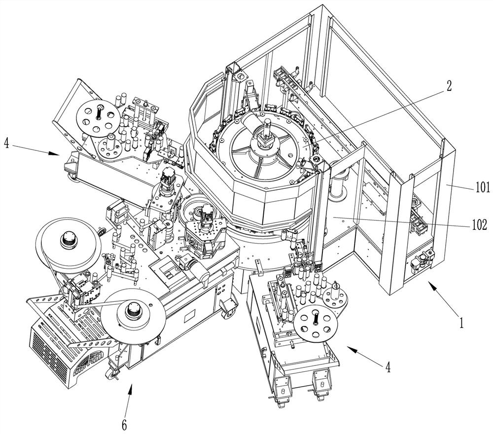
[0031] Such as figure 1 As shown, a combined labeling machine includes a frame 1, a bottle holder device 2, a hot melt adhesive label station trolley 6 and two self-adhesive label station trolleys 4;

[0032] The frame 1 includes an outer frame 101 and a table panel 102, the bottle holder device 2 is arranged on the table panel 102, the hot-melt adhesive label station trolley 6 is arranged at the front end of the frame 1, and the two self-adhesive label station trolleys 4 are arranged on the hot-melt label station. Both sides of the glue label station trolley 6; between the hot melt glue label station trolley 6 and the frame 1 and between the self-adhesive label station and the frame 1 are provided with connecting devices 5 .

[0033] Such as Figure 4 As shown, the connection device 5 includes a concave platform fixing bracket 501, two conical concave platforms 502 fixed on the concave platform fixing bracket 501, two conical positioning bodies 503 matched with the two conic...


PUM


Abstract

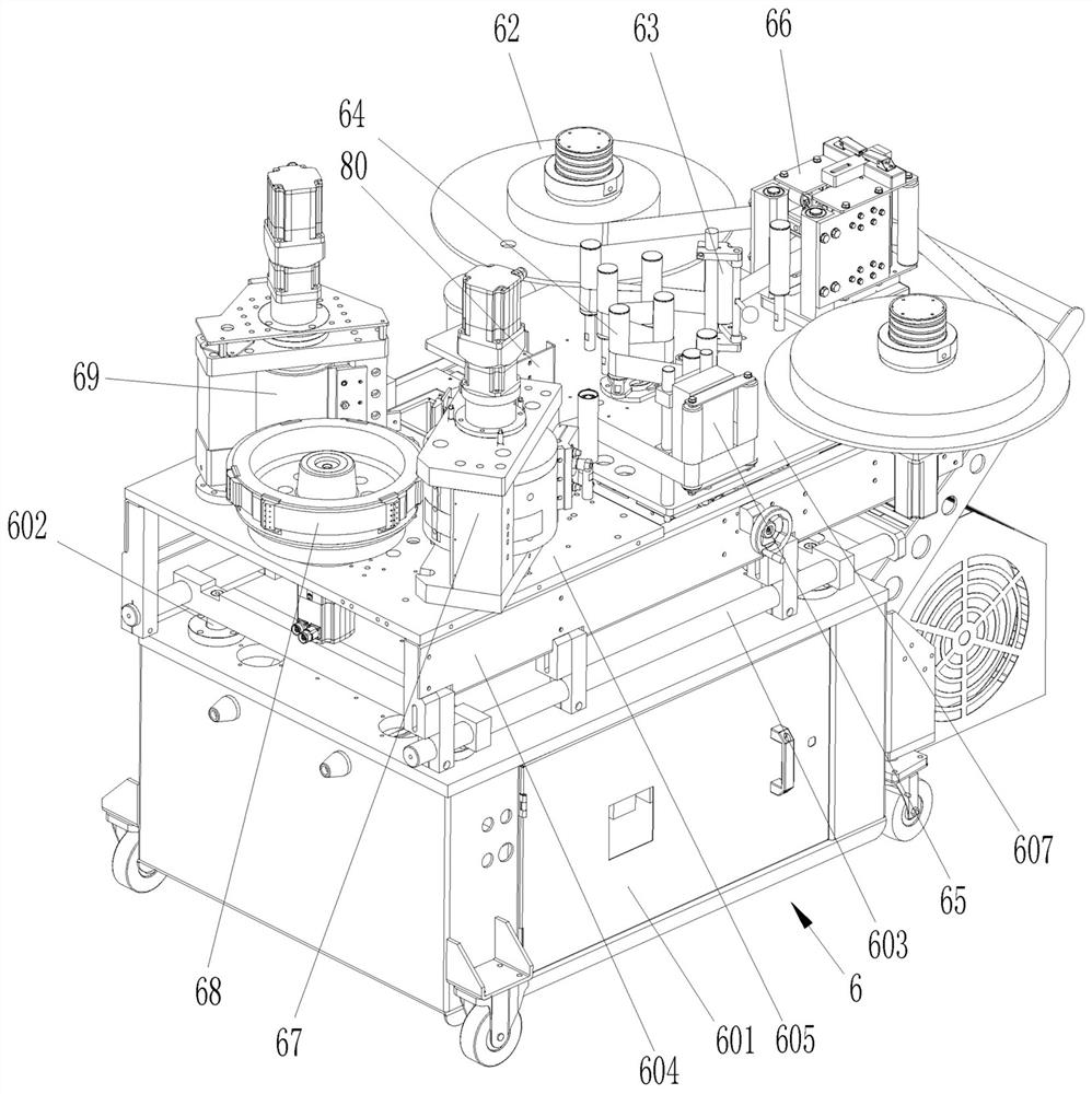
The invention discloses a lifting mechanism, a hot melt glue marking station trolley with the lifting mechanism and a combined type labeling machine.The combined labeling machine comprises a machine frame, a bottle supporting device, the hot melt glue marking station trolley and two non-adhesive labeling station trolleys; the lifting mechanism comprises a lifting base plate, a lifting component, atransmission belt and a driving mechanism; the lifting component comprises three or more lifting units arranged at the bottom of the lifting base plate, each lifting unit comprises a fixing seat, a hollow rotating shaft, a screw rod and a tooth-shaped belt wheel, wherein the bottom end of the rotating shaft extends out of the fixing seat, the tooth-shaped belt wheel sleeves the extending end of the rotating shaft, the screw rod is arranged in a hollow hole in the rotating shaft, an inner thread matched with the screw rod is arranged in the hollow hole in the rotating shaft, a rotation stopping boss is arranged at the upper end of the screw rod, and a rotation stopping hole matched with the rotation stopping boss is formed in the lifting base plate; and the transmission belt is meshed withthe tooth-shaped belt wheels, and the driving mechanism drives the conveying belt to drive the tooth-shaped belt wheels to rotate synchronously. By means of the scheme, single or combined use of multiple labels can be realized, and debugging is convenient.

Description

technical field [0001] The invention relates to the technical field of labeling, in particular to a lifting mechanism, a hot-melt glue labeling station trolley and a combined labeling machine. Background technique [0002] At present, in the bottled beverage industry, the demand for labels is becoming more and more diverse. Conventional labeling machines can only label one type of label. If you want to label other types of labels or combined labeling, you need Multiple devices to run, high cost and low production efficiency. [0003] Before the labeling station performs labeling operations, the height of each working part on the labeling station must be matched. The patent number is CN201010213017.7, and the Chinese invention patent named "Self-adhesive Integral Labeling Station" discloses a lifting mechanism. Self-adhesive overall labeling station, but its lifting mechanism needs to be individually adjusted for each lifting column, the operation is complicated, and the pra...

Claims


Application Information

Patent Timeline
Patent Type & Authority Patents(China)
IPC IPC(8): B65C3/08B65C9/02B65C9/18B65C9/44B65H20/02B65H23/26B65H18/08B65H26/00
CPCB65C3/08B65C9/02B65C9/18B65C9/44B65H18/08B65H20/02B65H23/26B65H26/00B65H2701/192
Inventor 刘远强徐伟尹乾刚袁烨周桄锥甘俊鑫
Owner 广州市万世德智能装备科技有限公司
Learn More