
Apparatus and method for controlling braking pressure of powered booster brake system

A brake pressure and brake system technology, which is applied in the direction of brake transmission device, brake action activation device, brake pressure measurement, etc., can solve the problems of increased computing load, reduced pressure control performance, and reduced braking feeling. To achieve the effect of reducing computing load, improving control performance and stability, and improving control performance and stability

Active Publication Date: 2017-12-08
HL MANDO CORP
View PDF7 Cites 7 Cited by
  • Summary
  • Abstract
  • Description
  • Claims
  • Application Information

AI Technical Summary

Problems solved by technology

[0006] However, the conventional electric power brake system as described above needs to continuously detect the pressure in the cylinder while driving the motor, and the ECU needs to constantly compare the detected pressure in the cylinder with the brake pressure, thus causing a calculation load Increased pressure control performance will be reduced, compared with the existing mechanical vacuum brake system, there is a problem that the braking feeling is reduced

Method used


Image

  • Apparatus and method for controlling braking pressure of powered booster brake system
  • Apparatus and method for controlling braking pressure of powered booster brake system
  • Apparatus and method for controlling braking pressure of powered booster brake system

Examples


Embodiment Construction

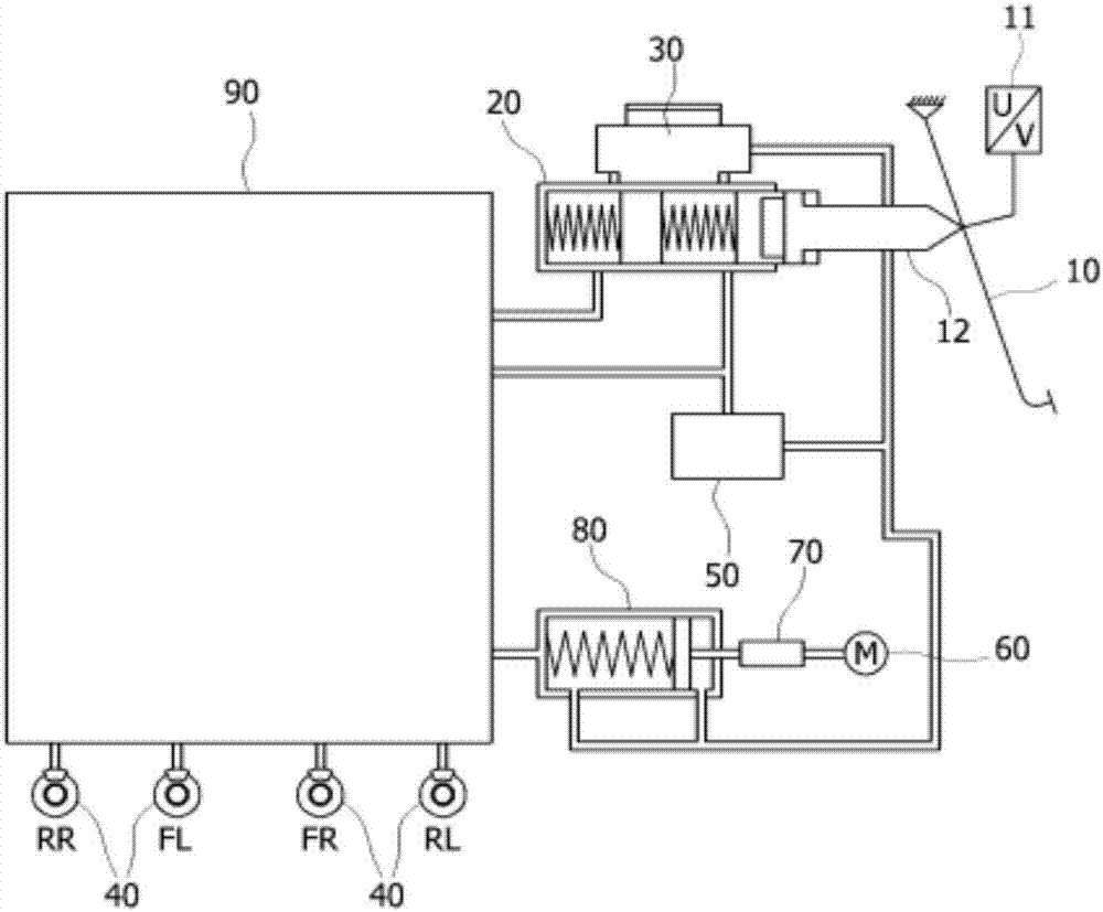
[0037] Hereinafter, preferred embodiments of the present invention will be described in detail with reference to the accompanying drawings, in which the same or similar structural components are assigned the same reference numerals regardless of the reference numerals, and repeated description thereof will be omitted.

[0038] In addition, when describing the present invention, if it is considered that the specific description of related known technologies may obscure the gist of the present invention, the detailed description will be omitted. Moreover, it should be pointed out that the accompanying drawings are provided for easier understanding of the idea of ​​the present invention, so the idea of ​​the present invention should not be limited to the accompanying drawings for interpretation.

[0039] Before describing the actuator assembly of the electric braking device of various embodiments of the present invention, firstly, reference will be made to figure 1 The integrated...


PUM


Abstract

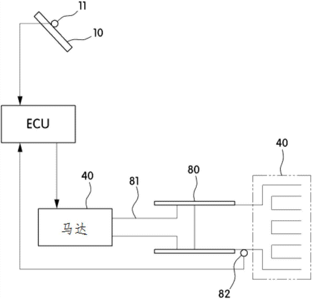
The present disclosure relates to an apparatus and a method for controlling a braking pressure of a powered booster brake system, the apparatus including a pedal stroke sensor configured to detect a manipulation degree of a brake pedal; an electronic control unit (ECU) configured to calculate a braking pressure using the detection result of the pedal stroke sensor; and a motor configured to move a piston inside a pump to perform a braking operation under control of the ECU, wherein the ECU determines a first position of the piston, which corresponds to the braking pressure, and controls the motor on the basis of a position of the piston.

Description

technical field [0001] The present invention relates to a brake pressure control device and method for an electric power-assisted braking system, in particular to a braking pressure control device for an electric power-assisted braking system capable of achieving the same braking feeling as a mechanical brake system and methods. Background technique [0002] In general, an electric power-assisted braking system is a braking system that effectively utilizes regenerative braking to improve the electric efficiency or fuel efficiency of an electric vehicle (EV) or a hybrid electric vehicle (HEV), and at the same time can feel a good braking feeling . [0003] The electric power-assisted braking system includes: a pedal travel sensor, which detects the operation of the brake pedal (Brake pedal); an electronic control unit (ECU), which converts the pressure detected by the pedal travel sensor into brake pressure, and The dynamic pressure controls the driving part of the driving ...

Claims


Application Information

Patent Timeline
Patent Type & Authority Applications(China)
IPC IPC(8): B60T13/74B60T13/66
CPCB60T13/66B60T13/74B60T7/042B60T8/4081B60T2270/82B60T2220/04B60T13/741B60T13/745B60T2270/88B60T8/172B60T13/166B60T13/20B60T13/662B60T17/02
Inventor 金荣材
Owner HL MANDO CORP
Learn More