Tunnel drying system and drying method

A drying system and tunnel technology, applied in drying, drying machine, drying gas arrangement, etc., can solve the problems of high pollution, low heat energy utilization rate, and large environmental impact, so as to reduce energy consumption, save energy, improve The effect of heat utilization

Active Publication Date: 2017-12-08
烟台明辉热泵节能科技有限公司
View PDF5 Cites 3 Cited by
  • Summary
  • Abstract
  • Description
  • Claims
  • Application Information

AI Technical Summary

Problems solved by technology

[0004] The present invention provides a tunnel drying system and a drying method in order to solve the problems of high cos...

Method used


Image

  • Tunnel drying system and drying method
  • Tunnel drying system and drying method
  • Tunnel drying system and drying method

Examples


Embodiment 1

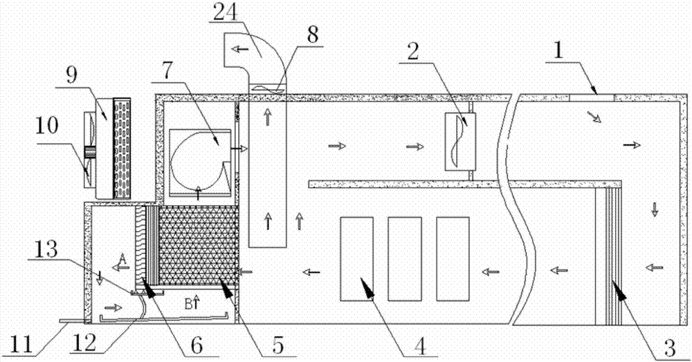
[0056] Tunnel drying system, including circulating air duct, circulating fan 2 located in the circulating air duct, dehumidifying fan 7 located in the circulating air duct, full heat exchange core 5 located in the circulating air duct and heat pump unit, multiple sets of circulating fans can be arranged side by side , the present invention can use one or more sets of heat pump units according to the situation.

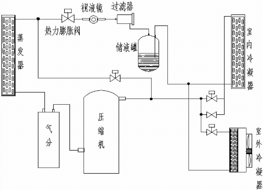
[0057] The heat pump unit includes a compressor, an indoor condenser 3, a throttling device, and an evaporator 6. The outlet of the compressor is connected to the inlet of the compressor through the indoor condenser 3, the throttling device, and the evaporator 6 in sequence. Both the indoor condenser 3 and the evaporator 6 are located in the circulating air duct.

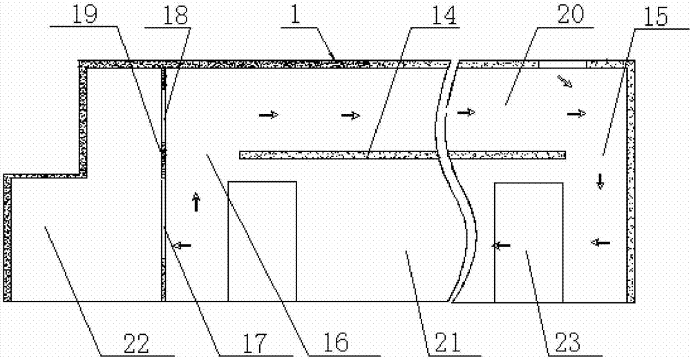
[0058] The circulating air duct is formed by separating the chamber body and several partitions, specifically, as figure 2 , the chamber body is divided into a first chamber body 22 and a second chamber bo...

Embodiment 2

[0070] On the basis of Embodiment 1, preferably, the tunnel drying system further includes an exhaust pipeline 24 equipped with a negative pressure fan 8; the inlet of the exhaust pipeline 24 is located between the material to be dried 4 and the Between the air inlets of the air duct A of the total heat exchange core 5 , the outlet of the air exhaust pipeline 24 is located outside the circulating air duct. The entrance position of the air exhaust pipeline 24 is selected because the air circulation in the circulating air duct is blown from the condenser side to the evaporation side. After the relatively dry air on the condensation side reaches the evaporation side, it becomes moisture with a high relative humidity, and the water vapor evaporated from the material will be absorbed in the middle. Therefore, the negative pressure fan 8 of the exhaust pipeline 24 not only pumps the most humid gas to the outside, but also makes the air pressure in the entire circulating air duct low...

Embodiment 3

[0073] On the basis of Embodiment 1 or 2, preferably, the heat pump unit further includes an outdoor condenser 9, the outdoor condenser 9 is installed outside the circulating air duct, and the indoor condenser 3 and the outdoor condenser 9 are connected in parallel . The heat pump unit also includes an outdoor fan 10 for cooling the outdoor condenser 9 .

[0074] In this way, step 3] of the control method of Embodiment 3 can still adopt the steps of Embodiment 1, and can also adopt the following steps: start the dehumidification fan and compressor, the indoor condenser and evaporator start to work, and the moisture in the air condenses into water droplets When the current "condensing side temperature" measured by the sensor reaches the "upper temperature limit of the current period", the compressor may not be turned off, but the outdoor condenser 9 and the outdoor fan 10 are started, that is, the outdoor condensing side is turned on immediately. The solenoid valve in the bran...


PUM


Abstract

The invention provides a tunnel drying system and drying method. The tunnel drying system comprises a circulating air duct, a circulating fan, a dehumidifying fan, a full-heat-exchanging core body and a heat pump unit. Materials to be dried are located between an indoor condenser and the air inlet side of an air duct A of the full-heat-exchanging core body. An evaporator is located on one side of an air outlet of the air duct A of the full-heat-exchanging core body. The air outlet of the air duct A of the full-heat-exchanging core body communicates with an air inlet of an air duct B of the full-heat-exchanging core body. The humidifying fan is located at the air outlet position of the air duct B of the full-heat-exchanging core body. After air of the air outlet side of the circulating fan passes through the indoor condenser and the materials to be dried in sequence, part of the air directly returns to the air inlet side of the circulating fan, and part of the air returns to the air inlet side of the circulating fan after passing through the air duct A of the full-heat-exchanging core body, the evaporator, the air duct B of the full-heat-exchanging core body and the dehumidifying fan. The tunnel drying system is low in cost, free of pollution and high in heat energy utilization rate, and is not influenced by environment.

Description

technical field [0001] The invention relates to the technical field of tunnel drying, in particular to a tunnel drying system and a drying method. Background technique [0002] At present, with the gradual development of the food industry, the freshness and taste of food have become one of the ways most consumers choose. Therefore, food drying has become an emerging industry. In this process, food is dehydrated and preserved to extend the shelf life of food. , and can add auxiliary materials in the early pretreatment process to improve the taste of food. In the traditional process, large-scale drying equipment uses boiler steam to increase the temperature to make food achieve the effect of drying. There are also many products that use air-drying and drying Drying and other methods are used to remove water, and boilers are used for drying. In the process of burning coal, a large number of particles are produced, which causes huge pollution to the environment. The most obviou...

Claims


Application Information

Patent Timeline
IPC IPC(8): F26B21/04F25B41/06A23L3/40F25B41/30
CPCA23L3/40F26B21/04F25B41/30Y02P60/85Y02P70/10
Inventor 迟永江项庆康常新华
Owner 烟台明辉热泵节能科技有限公司
Why Eureka
Try Eureka