
Automobile vibration fault detection system and detection data analysis method thereof

A technology for fault detection and data detection, which is used in vehicle testing, measuring devices, and machine/structural component testing. It can solve the problems of small processor data storage capacity, low data processing accuracy, and high processor energy consumption. , to achieve the effect of saving troubleshooting time, fast data processing, and large data storage capacity

Inactive Publication Date: 2017-12-08
SOUTHWEST UNIVERSITY
View PDF10 Cites 13 Cited by
  • Summary
  • Abstract
  • Description
  • Claims
  • Application Information

AI Technical Summary

Problems solved by technology

[0005] First, the vibration detection instrument processor has shortcomings such as small data storage capacity, single data processing function, full processing data, and weak real-time performance; and the processor consumes a lot of energy and has low performance
[0006] Second, the data acquisition and data transmission of portable instruments are complicated. When the data line is disconnected, the problem of connection interruption is prone to occur.
[0007] Third: The existing technology often uses single-chip processors for data processing, which cannot meet the current requirements for processor operation and data processing speed
[0008] Fourth: The accuracy of data processing is low, the cause and source of vibration cannot be directly obtained, and the workload of the staff is heavy

Method used


Image

  • Automobile vibration fault detection system and detection data analysis method thereof
  • Automobile vibration fault detection system and detection data analysis method thereof
  • Automobile vibration fault detection system and detection data analysis method thereof

Examples


Embodiment Construction

[0078] The specific implementation manner and working principle of the present invention will be further described in detail below in conjunction with the accompanying drawings.

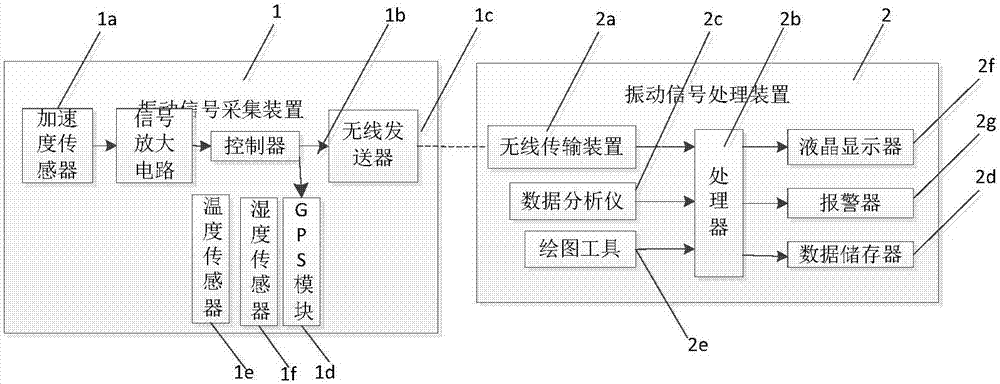
[0079] From figure 1 It can be seen that a vehicle vibration fault detection system is characterized in that: comprising a vibration signal acquisition device 1 and a vibration signal processing device 2;

[0080] Described vibration signal acquisition device 1 is arranged on the automobile, and described vibration signal acquisition device 1 comprises a plurality of acceleration sensors 1a, and described acceleration sensor 1a is connected with the vibration signal input end of controller 1b, and wirelessly connected to controller 1b The sending end is connected with a wireless transmitter 1c. Wherein each acceleration sensor 1a is arranged at different positions of the car, and is used for detecting vibration signals of different devices, such as car engine, car battery, car shaft and so on.

[0...


PUM


Abstract

The invention discloses an automobile vibration fault detection system and a detection data analysis method thereof. The automobile vibration fault detection system comprises a vibration signal acquisition device and a vibration signal processing device. The vibration signal acquisition device is arranged on an automobile. The vibration signal acquisition device comprises at least one acceleration sensor which is connected with the vibration signal input end of a controller. The wireless transmitting end of the controller is connected with a wireless transmitter. The vibration signal processing device comprises a wireless transmission device which is used for receiving the vibration signal transmitted by the wireless transmitter. The wireless transmission device is connected with a processor. The processor is also connected with a data analyzer and a data storage device. The data analyzer is used for performing data analysis on the vibration signal. The data storage device is used for storing the vibration signal. The beneficial effects are that the automobile operation safety factor is great, the vibration signal detection accuracy is high, the vibration signal processing speed is fast and the maintenance speed is fast.

Description

technical field [0001] The invention relates to the technical field of automobile vibration fault detection, in particular to an automobile vibration fault detection system and a detection data analysis method. Background technique [0002] With the development of science and technology, the development of detection instruments has been greatly promoted, and the development of small portable detection instruments with compact mechanism, superior performance, low price and easy operation is particularly rapid. [0003] In the automotive field, when a car breaks down, the vibration signal often changes during the running of the car. In the prior art, it is often found that the car failure is only found when there is a defect in the car response during the driving operation, and the car failure cannot be reported in advance, and the safety factor is low during the driving process of the car. [0004] Currently on the market, vibration detection also has the following defects: ...

Claims


Application Information

Patent Timeline
IPC IPC(8): G01H17/00G01M17/007
CPCG01H17/00G01M17/007
Inventor 李华青袁野吕庆国
Owner SOUTHWEST UNIVERSITY
Learn More