Supercharge Your Innovation With Domain-Expert AI Agents!

Novel hydraulic dynamometer through flow structure

A hydraulic dynamometer and flow-through technology, which is applied in the measurement of electric power, parts and instruments of electrical measuring instruments, etc., can solve problems such as cavitation, and achieve the effects of improving accuracy, stable water flow characteristics and reducing volume.

Active Publication Date: 2017-12-08
中国船舶重工集团公司第七0三研究所
View PDF10 Cites 0 Cited by
  • Summary
  • Abstract
  • Description
  • Claims
  • Application Information

AI Technical Summary

Problems solved by technology

However, due to the limitation of the blade structure, this kind of dynamometer has serious cavitation phenomenon, especially under the condition of high speed, so it cannot meet the power measurement requirements of the prime mover at a higher speed. matching measurement

Method used


Image

  • Novel hydraulic dynamometer through flow structure

Examples


Embodiment Construction

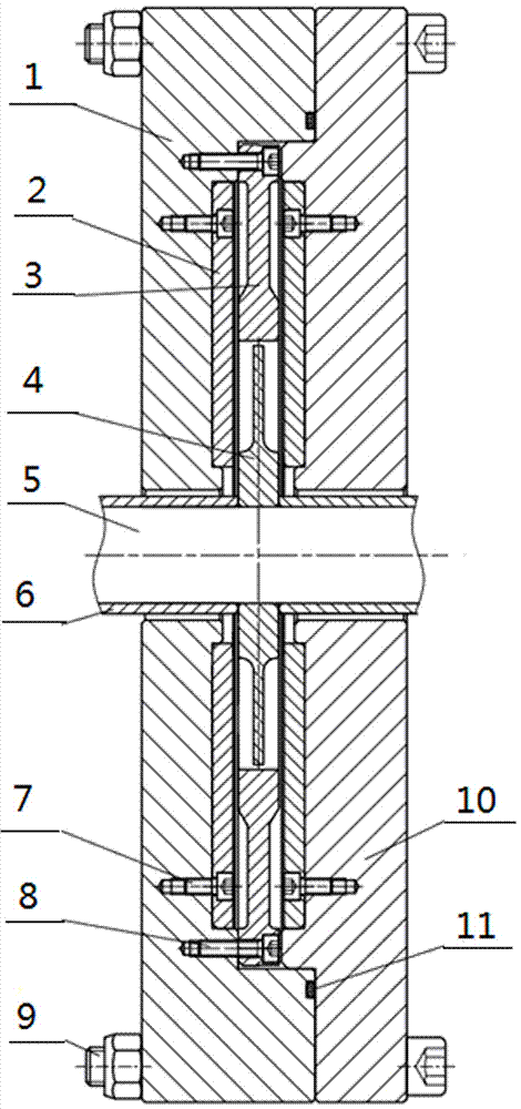
[0007] refer to figure 1 , a new type of hydraulic dynamometer flow structure, which includes a left half shell 1, a partition 2, a stator 3, a rotor 4, a main shaft 5, a shaft sleeve 6, a first connecting bolt 7, a second connecting bolt 8, The third connecting bolt 9, the right half shell 10 and the sealing ring 11, the partition plate 2 is respectively fixed on the left half shell 1 and the right half shell 10 by the first connecting bolt 7, the stator 3 is fixed by the second connecting bolt 8 On the left half shell 1, the left half shell 1 and the right half shell 10 are connected by the third connecting bolt 9 to form the stator water chamber of the flow part of the hydraulic dynamometer, the left half shell 1 and the right half shell The middle of the body 10 is sealed by a sealing ring 11, and the rotor 4 is fixed on the main shaft 5 through the sleeve 6 to form a dynamometer rotor assembly.

[0008] According to the absorbed power of the hydraulic dynamometer and the...


PUM


Abstract

The invention relates to a hydraulic dynamometer through flow form, specifically to a novel hydraulic dynamometer through flow structure. The structure includes a left half shell, a separator plate, a stator, a rotor, a main shaft, a shaft sleeve, first connecting bolts, a second connecting bolt, a third connecting bolt, a right half shell and a sealing ring. The separator plate is fixed to the left half shell and the right half shell through the first connecting bolts separately, the stator is fixed to the left half shell through the second connecting bolt, and the left half shell and the right half shell are connected through the third connecting bolt, thereby forming a stator water chamber of a hydraulic dynamometer through flow part, the middle between the left half shell and the right half shell is sealed through the sealing ring, and the rotor is fixed to the main shaft through the shaft sleeve, thereby forming a dynamometer rotor assembly. Compared with a traditional blade type hydraulic dynamometer, since a water flow characteristic in the water chamber in a power absorbing process is relatively stable, occurrence of a cavitation phenomenon is reduced; a system is simplified and intermediate link power loss is reduced, cost is saved, and precision of measurement is improved.

Description

Technical field: [0001] The invention relates to a flow form of a hydraulic dynamometer, in particular to a novel flow structure of a hydraulic dynamometer. Background technique: [0002] Hydraulic dynamometer is currently widely used in various prime mover power testing fields. As the effective load of the prime mover load test, it can measure the output power of the prime mover, and at the same time cooperate with the prime mover to perform various operating point conversion tests. At present, the rotor and stator of common hydraulic dynamometers are in the form of blades. When measuring the power of the prime mover, the rotor follows the rotation of the prime mover and stirs the water entering the dynamometer. The water transmits the torque to the stator and the casing, and drives the stator. The housing rotates at a small angle relative to the base of the dynamometer. The movement trend of the stator and housing components is prevented by the tension and pressure sensor ...

Claims


Application Information

Patent Timeline
Patent Type & Authority Applications(China)
IPC IPC(8): G01R21/00G01R1/02
CPCG01R1/02G01R21/00Y02E10/20
Inventor 宋成林赵少华张元锋梁小光
Owner 中国船舶重工集团公司第七0三研究所
Features
  • R&D
  • Intellectual Property
  • Life Sciences
  • Materials
  • Tech Scout
  • Unparalleled Data Quality
  • Higher Quality Content
  • 60% Fewer Hallucinations
Learn More