
A dynamical machine experimental instrument driven by ampere force and electrostatic force

An electrostatic force and power machine technology, applied in the field of physical experimental instruments, can solve the problems of unutilized current and lack of electrostatic power machine design and equipment.

Active Publication Date: 2019-08-23
QIQIHAR UNIVERSITY
View PDF7 Cites 0 Cited by
  • Summary
  • Abstract
  • Description
  • Claims
  • Application Information

AI Technical Summary

Problems solved by technology

Over the years, in order to help students correctly understand this concept and apply electrostatic induction, some demonstration experiments have been set up in conjunction with teaching, such as electrostatic jumping ball experiment, electrostatic pendulum ball experiment, electrostatic roller experiment, electrostatic blower, and the scale static electricity sensor designed by the inventor of this patent. Jumping ball tester, swing electrostatic power machine, etc. Although the existing electrostatic demonstration devices have solved some needs to a certain extent, they lack further development and innovation of electrostatic power demonstration experiments. As power machines, the demonstration power machines currently seen mainly include : Power machines such as heat engine, electric motor (ampere force drive), standing wave motor, etc., these have its unique advantage and limitation, lack the design and the device that effectively realize electrostatic power machine aspect, especially the electric current that forms when charge exchange in the electrostatic power machine experiment does not have. How to realize that the rotating plate is a flat plate to obtain a continuous co-direction driven electrostatic power machine and the current formed during the charge exchange is utilized, this patent will solve this problem

Method used


Image

  • A dynamical machine experimental instrument driven by ampere force and electrostatic force
  • A dynamical machine experimental instrument driven by ampere force and electrostatic force
  • A dynamical machine experimental instrument driven by ampere force and electrostatic force

Examples


Embodiment Construction

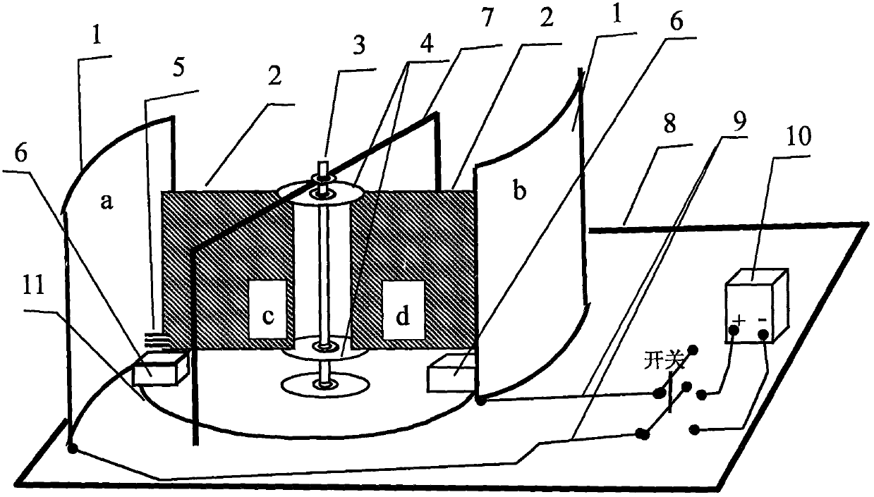
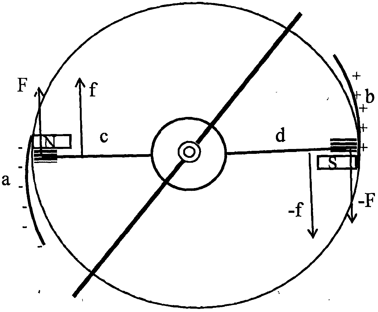
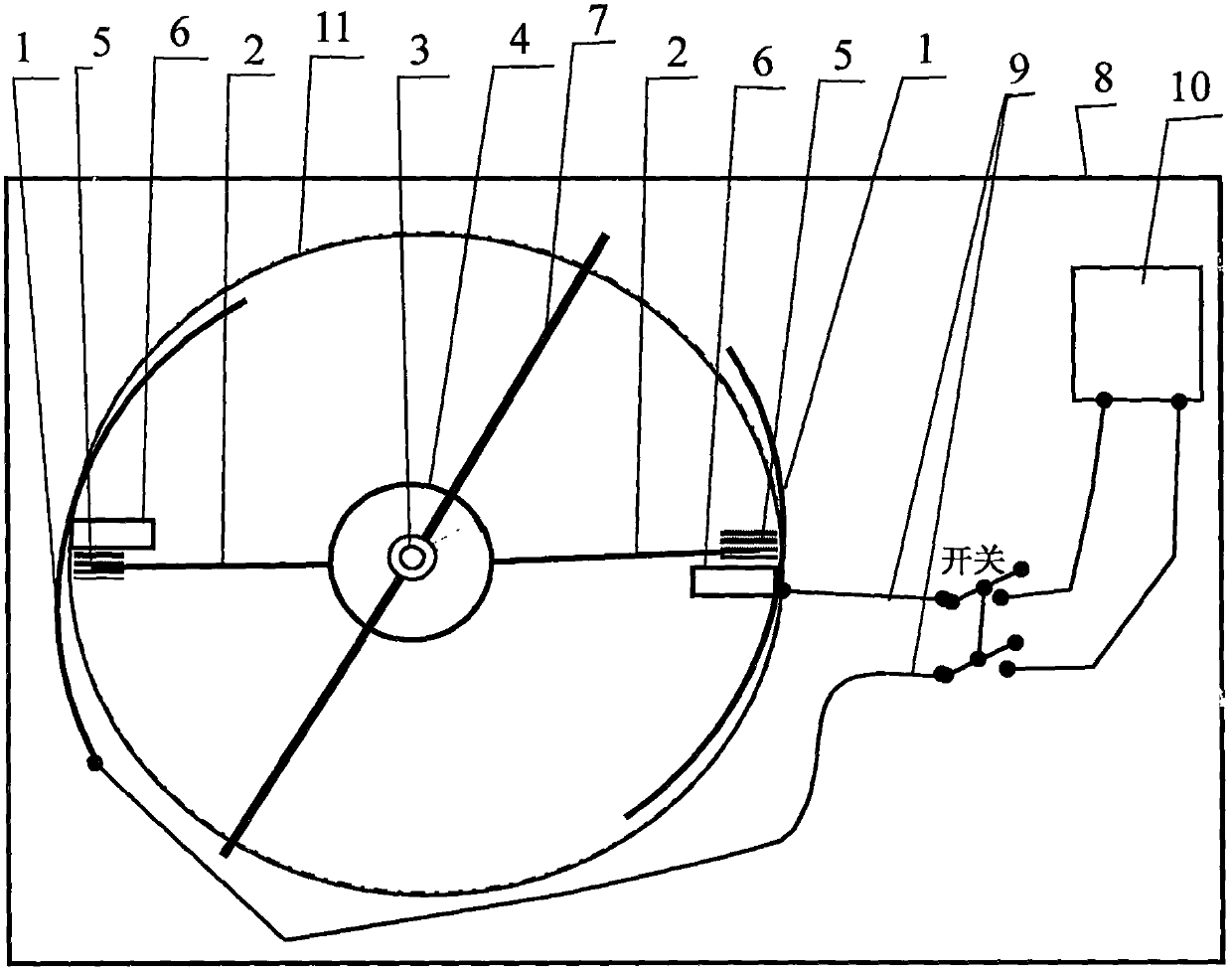
[0020] as attached figure 1 , attached image 3: A power machine experimental instrument driven by ampere force and electrostatic force, mainly composed of an electrode plate 1, a rotating plate 2, a plastic turntable shaft 3, a plastic turntable 4, a charge exchange brush 5, a permanent magnet 6, a bracket 7, and a high-density insulating plate 8 , a connecting wire 9, and a high-voltage electrostatic power supply 10 are characterized in that: the electrode plate 1 includes a metal conductor plate a, a metal conductor plate b, a metal conductor plate a and a metal conductor plate b (cut from the metal conductor shell of a thermos bottle ) are cylindrical electrode plates, and the electrode plate 1 is vertical and fixed on the high-density insulating plate 8; the rotating plate 2 is a non-ferromagnetic metal conductor flat c (mesh shape Aluminum plate) and metal conductor flat d (mesh aluminum plate), the metal conductor flat c and the metal conductive flat d are connected a...


PUM


Abstract

An ampere force and electrostatic force driving power machine experimental instrument is mainly composed of an electrode plate, a rotating plate, a plastic turntable rotating shaft, a plastic turntable, a charge exchange brush, a permanent magnet and a high-voltage electrostatic power supply, and lays emphasis on the technologies of realizing the continuous electrostatic force driving via the electrode plate which is a cylindrical metal conductor plate and the rotating plate which is a nonferromagnetic metal conductor flat plate, and converting a current formed at the charge exchange of the rotating plate and the electrode plate into the ampere force driving. The experimental design facilitates promoting the cultivation of the innovation spirit and practical ability of the students better. The experimental instrument is very simple and easy to manufacture, is obvious in effect, adds more education functions in the teaching, and is a piece of work having great significance and development prospect.

Description

technical field [0001] The application relates to a production and demonstration method of an experimental instrument driven by ampere force and electrostatic force, belonging to the field of physical experiment instruments. Background technique [0002] In college physics courses, static electricity is an important content, and the application of electrostatic induction is the content that everyone pays attention to. Over the years, in order to help students correctly understand this concept and apply electrostatic induction, some demonstration experiments have been set up in conjunction with teaching, such as electrostatic jumping ball experiment, electrostatic pendulum ball experiment, electrostatic roller experiment, electrostatic blower, and the scale static electricity sensor designed by the inventor of this patent. Jumping ball tester, swing electrostatic power machine, etc. Although the existing electrostatic demonstration devices have solved some needs to a certain ...

Claims


Application Information

Patent Timeline
Patent Type & Authority Patents(China)
IPC IPC(8): G09B23/18
Inventor 梁法库刘道森陈永斌
Owner QIQIHAR UNIVERSITY
Learn More