Cascade full-bridge direct-current breaker

A DC circuit breaker, cascading technology, applied in circuit devices, emergency protection circuit devices for limiting overcurrent/overvoltage, emergency protection circuit devices, etc., can solve the problem of increasing the number of DC circuit breaker components, capacitor storage voltage Difficult to quickly release, large leakage current circuit breaker and other problems, to simplify the breaking and closing control, eliminate the risk of direct short circuit, and achieve the effect of overvoltage suppression

Inactive Publication Date: 2017-12-08
GLOBAL ENERGY INTERCONNECTION RES INST CO LTD +2
View PDF7 Cites 9 Cited by
  • Summary
  • Abstract
  • Description
  • Claims
  • Application Information

AI Technical Summary

Problems solved by technology

However, after the breaking is completed, the internal capacitor storage voltage of each module unit is difficult to release quickly, resulting in the risk of direct short circuit and damage to the DC circuit breaker in the fast reclosing application.
In addition, the relatively large leakage current after the circuit breaker is broken, resulting in high heat generation of the internal discharge resistance of the circuit breaker, also needs to be further optimized
Moreover, the existing cascaded full-bridge DC breaker solves the above-mentioned technical problems faced by adding diodes in the full-bridge module, but increases the number of components used in the DC breaker, which is not conducive to reducing cost and overall volume

Method used


Image

  • Cascade full-bridge direct-current breaker
  • Cascade full-bridge direct-current breaker
  • Cascade full-bridge direct-current breaker

Examples


Embodiment 1

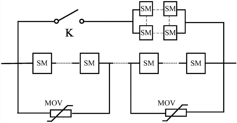
[0040] The structural diagram of the cascaded full-bridge DC circuit breaker provided by Embodiment 1 of the present invention is as follows figure 1 as shown, figure 1 SM in the formula means a full-bridge module, MOV means a lightning arrester, and K means a mechanical switch. The cascaded full-bridge DC circuit breaker mainly includes a parallel main flow branch, a transfer current branch and an energy absorption branch;

[0041] The above-mentioned main flow branch includes a matrix module composed of full-bridge modules in a matrix form and a mechanical switch connected in series with the full-bridge module;

[0042] The above-mentioned transfer current branch includes N full-bridge modules connected in series in sequence, N≥1, that is, at least one full-bridge module connected in series on the transfer current branch is set;

[0043] The above-mentioned energy absorbing branch includes M lightning arresters connected in series in sequence, M≥1, that is, at least one lig...

Embodiment 2

[0054] Embodiment 2 of the present invention provides a cascaded full-bridge DC circuit breaker, which mainly includes a parallel main flow branch, a transfer current branch and an energy absorption branch;

[0055] The above-mentioned main flow branch includes a matrix module composed of full-bridge modules in a matrix form and a mechanical switch connected in series with the full-bridge module;

[0056] The above-mentioned transfer current branch includes N full-bridge modules connected in series in sequence, N≥1, that is, at least one full-bridge module connected in series on the transfer current branch is set;

[0057] The above-mentioned energy absorbing branch includes M lightning arresters connected in series in sequence, M≥1, that is, at least one lightning arrester connected in series in sequence on the energy absorbing branch is provided.

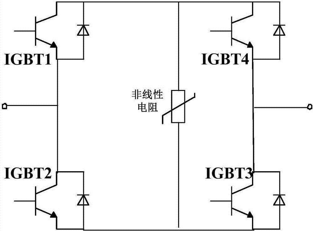
[0058] The above-mentioned full-bridge module adopts a bridge arm circuit formed by a fully controlled device, and the bridge ar...

Embodiment 3

[0063] Embodiment 3 of the present invention provides a cascaded full-bridge DC circuit breaker, which mainly includes a parallel main flow branch, a transfer current branch and an energy absorption branch;

[0064] The above-mentioned main flow branch includes a matrix module composed of full-bridge modules in a matrix form and a mechanical switch connected in series with the full-bridge module;

[0065] The above-mentioned transfer current branch includes N full-bridge modules connected in series in sequence, N≥1, that is, at least one full-bridge module connected in series on the transfer current branch is set;

[0066] The above-mentioned energy absorbing branch includes M lightning arresters connected in series in sequence, M≥1, that is, at least one lightning arrester connected in series in sequence on the energy absorbing branch is provided.

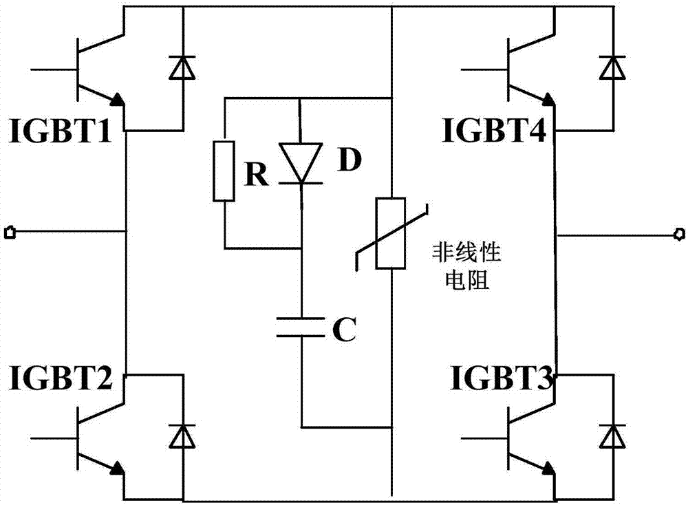
[0067] The above-mentioned full-bridge module adopts a bridge arm circuit formed by a fully controlled device, and the bridge ar...


PUM


Abstract

The invention provides a cascade full-bridge direct-current breaker. The cascade full-bridge direct-current breaker comprises a main through-flow branched circuit, a transfer branched circuit and an energy absorption branched circuit which are in parallel; the main through-flow branched circuit comprises a first full-bridge module and a mechanical switch which are connected in series; the transfer branched circuit comprises N second full-bridge modules which are connected in series successively; the energy absorption branched circuit comprises M lightning arresters; and the full-bridge modules adopt bridge-arm circuits or diode bridge-arm circuits composed of full-control devices. Through the technical scheme provided in the invention, nonlinear resistance voltage sharing is adopted, the constitution form is greatly simplified, and the total cost and volume of the equipment are reduced; compact arrangement of the cascade full-bridge direct-current breaker is facilitated, the stray parameter is easily reduced, overvoltage inhibition is realized, the overall application reliability is improved, high-speed reclosing of the cascade full-bridge direct-current breaker in several milliseconds can be realized, the application range of the cascade full-bridge direct-current breaker is expanded, and the operation reliability and economical efficiency of a flexible multi-port and direct-current power grid are further improved.

Description

technical field [0001] The invention relates to the technical field of power electronics, in particular to a cascaded full-bridge DC circuit breaker. Background technique [0002] With the application of multi-terminal flexible DC and DC grid technology based on voltage source converters, high-voltage DC circuit breakers have become one of the key equipment to ensure the stable, safe and reliable operation of the system. Mixed use of mechanical switches and fully-controlled power electronic switch DC circuit breaker technology combines the low loss characteristics of mechanical switches and the fast breaking characteristics of power electronic switches. It is currently the most effective technical approach for DC breaking in high-voltage transmission systems. When high-voltage DC circuit breakers are applied to flexible multi-terminal DC and DC power grids with large capacity overhead lines, in addition to the characteristics of fast and low loss, they should also have stron...

Claims


Application Information

Patent Timeline
Patent Type & Authority Applications(China)
IPC IPC(8): H02H7/26H02H9/04
CPCH02H7/268H02H9/042
Inventor 周万迪贺之渊魏晓光张升赵岩刘远
Owner GLOBAL ENERGY INTERCONNECTION RES INST CO LTD
Why Eureka
Try Eureka