Flexible Multilevel Bridgeless Power Factor Correction Converter and Modulation Method

A technology of power factor correction and modulation method, applied in output power conversion devices, high-efficiency power electronic conversion, electrical components, etc., can solve the problem of large inductor current high-frequency switching ripple, increased diode rectifier bridge on-state loss, unfavorable conversion In order to improve the converter efficiency and reduce the heat generation of the inductor,

Active Publication Date: 2020-04-03
HUBEI UNIV OF TECH
View PDF2 Cites 0 Cited by
  • Summary
  • Abstract
  • Description
  • Claims
  • Application Information

AI Technical Summary

Problems solved by technology

This circuit is easy to implement and has high reliability, but there are two problems: 1) In one switching cycle, the voltage change at both ends of the inductor is the output voltage, and when the output voltage amplitude is large, the high-frequency switching ripple of the inductor current is large; 2) The on-state loss of the diode rectifier bridge accounts for a large proportion of the total loss of the converter (about 30% to 60%). When the input voltage is low, the on-state loss of the diode rectifier bridge also increases greatly
[0004] In order to solve the above problems, the three-level PFC circuit proposed in Chinese invention patent 201010138311.6 can reduce the volume of the inductor by about 50% under the premise of keeping the switching frequency consistent with the maximum allowable inductor current ripple, but there is still a diode rectifier bridge, so Does not address efficiency drop at low input voltage
The single-inductance three-level bridgeless power factor correction converter proposed in Chinese invention patent 201010039662.1 does not have a diode rectifier bridge, which can improve the efficiency of the converter at low input voltages, but there is a DC capacitor that is always In the discharge state, it is necessary to use a capacitor with a large capacity and volume, which is not conducive to improving the power density of the converter

Method used


Image

  • Flexible Multilevel Bridgeless Power Factor Correction Converter and Modulation Method
  • Flexible Multilevel Bridgeless Power Factor Correction Converter and Modulation Method
  • Flexible Multilevel Bridgeless Power Factor Correction Converter and Modulation Method

Examples


Embodiment Construction

[0036] The present invention will be further described in detail below in conjunction with the accompanying drawings and specific embodiments.

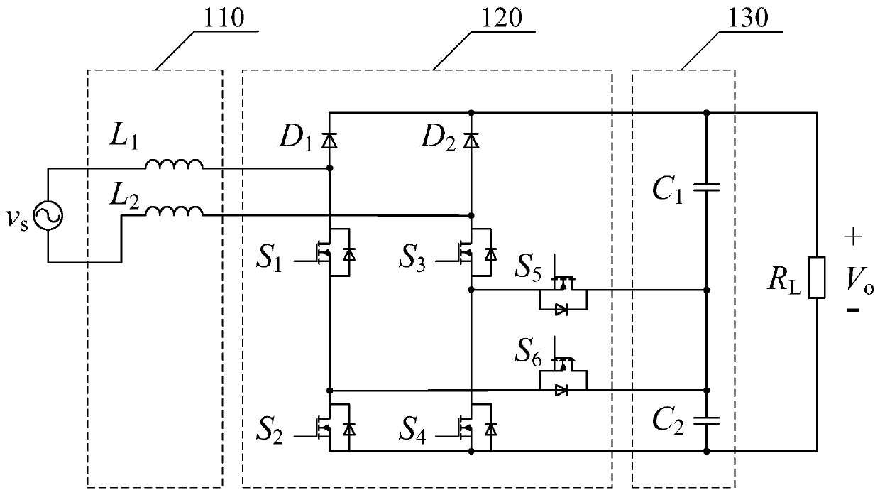
[0037] Such as figure 1 Shown is a flexible multilevel bridgeless power factor correction converter comprising an AC inductor section 110, a power electronic switching network 120 and a DC capacitor section 130.

[0038] The power electronic switch network 120 includes an N-channel MOSFET switch tube S 1 , N-channel MOSFET switch tube S 2 , N-channel MOSFET switch tube S 3 , N-channel MOSFET switch tube S 4 , N-channel MOSFET switch tube S 5 And N-channel MOSFET switch tube S 6 , and the diode D 1 and diode D 2 ; Among them, the diode D 1 The anode is connected to the N-channel MOSFET switch S 1 Drain, N-channel MOSFET switch S 1 The source is connected to the N-channel MOSFET switch S 2 Drain, N-channel MOSFET switch S 2 The source is connected to the N-channel MOSFET switch S 4 source; diode D 2 The anode is connected ...


PUM


Abstract

The invention relates to a flexible multi-level bridgeless power factor correction converter and a modulation method. The converter includes an AC inductance part, a power electronic switch network and a DC capacitor part; a diode D 1 The anode is connected to the switching tube S 1 Drain, switch tube S 1 The source is connected to the switching tube S 2 Drain; Diode D 2 The anode is connected to the switching tube S 3 Drain, switch tube S 3 The source is connected to the switching tube S 4 Drain; switch tube S 5 The source is connected to the switching tube S 3 Source; switch tube S 6 The source is connected to the switching tube S 1 source; diode D 1 Cathode and Diode D 2 The cathode is connected; the switch tube S 2 source and switch S 4 The source is connected; the switch tube S 5 drain and switch S 6 connected to the drain. It can reduce inductance loss and volume, reduce on-state loss at low input voltage, have smaller DC capacitance, and have higher power density; it can flexibly realize five-level and seven-level operation without changing the circuit structure state switch.

Description

technical field [0001] The invention belongs to the technical field of low on-state loss bridgeless power factor correction converters for low input voltage and high output voltage, and in particular relates to a flexible multi-level bridgeless power factor correction converter and a modulation method. Background technique [0002] The input stage of a switching power supply usually adopts an uncontrollable capacitive rectification circuit composed of diodes, but the input current waveform of this circuit contains a large number of low-order harmonic components, and the power factor of the circuit is very low, which causes serious pollution to the power grid. Power factor correction technology, namely PFC (Power Factor Correction), can control the input current waveform of the rectifier circuit to make it as close as possible to a sine wave and improve the power factor of the converter. Among them, the active power factor correction composed of fully-controlled power electro...

Claims


Application Information

Patent Timeline
Patent Type & Authority Patents(China)
IPC IPC(8): H02M1/42
CPCH02M1/4208H02M1/0048Y02B70/10Y02P80/10
Inventor 宫力蒋云昊丁稳房席自强
Owner HUBEI UNIV OF TECH
Why Eureka
Try Eureka